
System for controlling speed of scarifier working device and speed control method

A technology of working device and hydraulic control system, which is applied in the direction of earth mover/shovel, mechanically driven excavator/dredger, construction, etc., can solve the problem of lack of control system, shortened service life of parts, and damage of parts And other issues

Active Publication Date: 2018-01-16
SANY HEAVY MACHINERY
View PDF5 Cites 2 Cited by
  • Summary
  • Abstract
  • Description
  • Claims
  • Application Information

AI Technical Summary

Problems solved by technology

[0004] Therefore, when the ripper suddenly stops suddenly during the process of lifting the working device or the hydraulic cylinder reaches the limit position, the impact force generated by the ripper (this auxiliary working device) is much larger than that generated by the standard working device. The up and down vibration amplitude of the ripper excavator is also much larger, causing serious damage to important parts such as the hydraulic cylinder, frame and platform of the excavator, which in turn can lead to a serious shortening of the service life of these parts (that is, the shock generated by the working device of the ripper The force can only be absorbed by the hydraulic cylinder of the working device and related structures, resulting in a serious shortening of the service life of the hydraulic cylinder and related structural parts)
[0005] However, the control system of the ripper excavator in the prior art is not available, and the speed control subsystem and control method of the working device cannot reduce or avoid the impact of equipment damage caused by the impact force of the working device

Method used


Image

  • System for controlling speed of scarifier working device and speed control method
  • System for controlling speed of scarifier working device and speed control method

Examples


Embodiment Construction

[0070] The technical solutions of the present invention will be clearly and completely described below in conjunction with the accompanying drawings. Apparently, the described embodiments are some of the embodiments of the present invention, but not all of them. Based on the embodiments of the present invention, all other embodiments obtained by persons of ordinary skill in the art without making creative efforts belong to the protection scope of the present invention.

[0071] In the description of the present invention, it should be noted that some words indicating orientation or positional relationship are only for the convenience of describing the present invention and simplifying the description, rather than indicating or implying that the referred device or element must have a specific Orientation, construction and operation in a particular orientation, therefore should not be construed as limiting the invention.

[0072] In the description of the present invention, it s...


PUM


Abstract

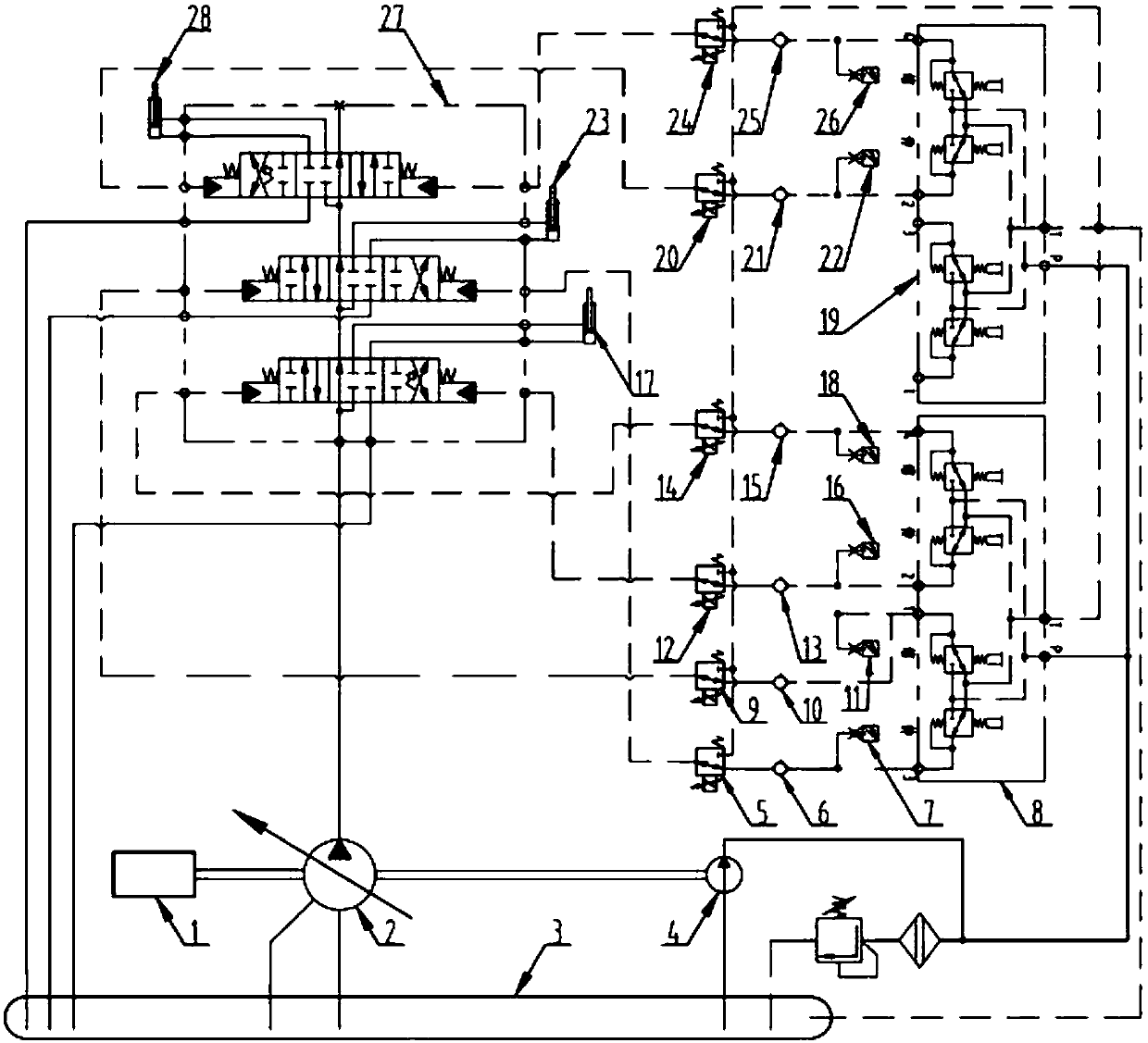
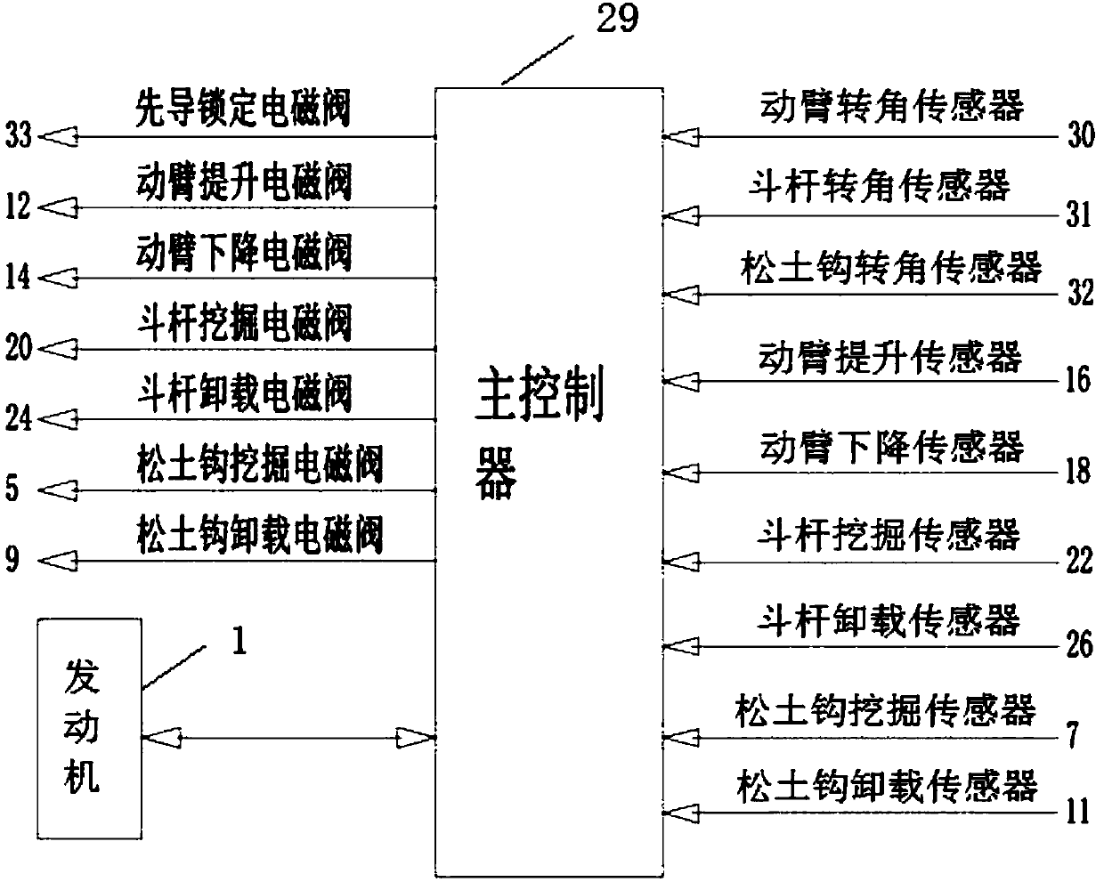
The invention discloses a system for controlling a speed of a scarifier working device and a speed control method. The system for controlling the speed of the scarifier working device comprises an electrical control system and a hydraulic control system, wherein the electrical control system comprises a master controller and further comprises a swing arm elevating sensor, a swing arm lowering sensor, a bucket rod digging sensor, a bucket rod unloading sensor, a scarification hook digging sensor and a scarification hook unloading sensor which are respectively and electrically connected with themaster controller; the electrical control system further comprises a swing arm rotation angle sensor, a bucket rod rotation angle sensor and a scarification hook rotation angle sensor which are electrically connected with the master controller. According to the system for controlling the speed of the scarifier working device and the speed control method provided by the invention, steady speed control of the swing arm, the bucket rod and the scarification hook can be ensured.

Description

technical field [0001] The invention relates to the technical field of heavy construction machinery equipment, in particular to a system and a speed control method for controlling the speed of a ripper working device. Background technique [0002] As we all know, a ripper is a working device with crushing and plowing functions. The working device can be installed on a standard excavator. At this time, the ripper installed on the excavator is a ripper for an excavator; [0003] As an important auxiliary working device of a large hydraulic excavator, the ripper, its boom, arm, connecting rod, rocker, tooth seat mounting plate, tooth seat and tooth tip are more advanced than the standard excavator working device. Durable, stronger and with a lot more weight. [0004] Therefore, when the ripper suddenly stops suddenly during the process of lifting the working device or the hydraulic cylinder reaches the limit position, the impact force generated by the ripper (this auxiliary wo...

Claims


Application Information

Patent Timeline
IPC IPC(8): E02F5/32E02F3/43
Inventor 叶旺盛程义鹏马卫强尹满义
Owner SANY HEAVY MACHINERY
Learn More