Adaptive mobile optical charging system based on feedback signaling

A charging system and self-adaptive technology, applied in current collectors, electric vehicles, electrical components, etc., can solve problems such as limited battery resources, and achieve the effect of ensuring charging safety, optimizing charging performance, and increasing flexibility

Inactive Publication Date: 2018-02-02
TONGJI UNIV
View PDF1 Cites 7 Cited by
  • Summary
  • Abstract
  • Description
  • Claims
  • Application Information

AI Technical Summary

Problems solved by technology

Due to the limitations of batteries in terms of capacity, weight, safety, etc., the potential of battery resources that can be tapped is already limited

Method used


Image

  • Adaptive mobile optical charging system based on feedback signaling
  • Adaptive mobile optical charging system based on feedback signaling
  • Adaptive mobile optical charging system based on feedback signaling

Examples


Embodiment 1

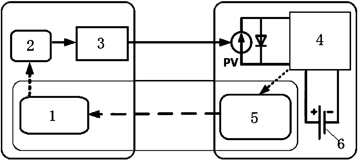
[0037] Such as figure 1 As shown, an adaptive mobile optical charging system based on feedback signaling includes a separate transmitting end and a receiving end. The transmitting end includes a feedback controller 1, a power supply 2 and an optical charging transmitter 3 connected in sequence, and the receiving end includes a sequentially connected Connected optical charging receiver, power converter 4 and feedback monitor 5, power converter 4 is connected to the battery 6 that needs to be charged, and battery 6 is a lithium ion battery in this embodiment; Optical charging transmitter 3 sends to the optical charging receiver The light beam transmits power energy, and the feedback monitor 5 is used to feed back the required information to the feedback controller 1 .

[0038] Such as figure 1 As shown, the optical charging transmitter 3 and the optical charging receiver form a mobile optical charging device, which transmits energy through a laser resonator located in free spac...

Embodiment 2

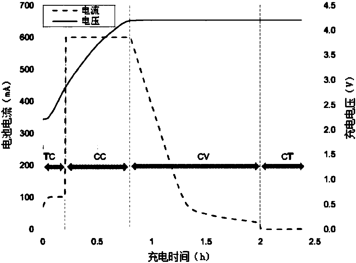
[0058] Assume that battery 6 is charged at the end of the CC phase, as image 3 shown in . The required current and voltage are 600mA and 4.2V, respectively. Therefore, the expected electric energy output power, that is, the output power of the photovoltaic cell panel should be 600mA×4.2V=2.52W. in search Figure 7 After that, the required laser irradiation intensity can be calculated, which is about 4W / cm 2 ,Depend on Figure 6 It can be obtained that the corresponding output current and voltage of the photovoltaic cell panel are 17mA and 148V, respectively. Set the expected laser power density 4W / cm by feedback 2 provided to Power Supply 2, which can then be based on Figure 4 Generate the desired laser power.

Embodiment 3

[0060] In most conventional wireless charging systems, including mobile optical charging systems without adaptive adjustment, the battery 6 can only be charged at a fixed power. based on image 3 According to the lithium-ion battery charging curve in the above, the lithium-ion battery needs a minimum power of 4.2W (constant voltage 4.2V and constant current 1A). Figure 8 The solid line in shows a constant 4.2W charging power. The charging power of the battery 6 in this system is determined by Figure 8 The dashed line in the dash gives, relying on image 3 The shown battery 6 charging curve traces, the gap between the constant power charging and the system is represented by a dashed line combined with bars and dots, which is the power saved by the system.

[0061] The integration of power over time produces electricity. After calculation, the constant power charging consumes 15.12Wh, and this system needs 5.98Wh, a difference of 9.14Wh, which means that this system can sa...


PUM


Abstract

The invention relates to an adaptive mobile optical charging system based on feedback signaling. The adaptive mobile optical charging system comprises a transmitting terminal and a receiving terminalwhich are separated, and is characterized in that the transmitting terminal comprises a feedback controller, a power supply and an optical charge transmitter which are sequentially connected, the receiving terminal comprises an optical charge receiver, an electric energy converter and a feedback monitor which are sequentially connected, and the electric energy converter is connected with a charging target; and the optical charge transmitter transmits optical beam transmission power energy to the optical charge receiver, and the feedback monitor is used for feeding back required information tothe feedback controller. Compared with the prior art, the adaptive mobile optical charging system achieves mobile optical charging within a scope of 0-50m; and the adaptive mobile optical charging system further achieves an information feedback mechanism between the transmitting terminal and the receiving terminal, and the transmitting terminal can respond according to the feedback information ofthe receiving terminal.

Description

technical field [0001] The invention relates to the field of optoelectronic engineering, in particular to an adaptive mobile optical charging system based on feedback signaling. Background technique [0002] According to the Cisco Visual Networking Index (VNI) report, wireless service traffic will increase by nearly 100% every year in the future, and wireless data traffic will increase by 1000 times in the next ten years. Subsequently, the information processing capabilities of wireless communication and mobile computing devices will also continue to increase, thus putting forward higher and higher requirements for the energy supply of mobile devices. Taking the current smart phone as an example, more than 70% of the volume and weight are occupied by batteries, and this proportion is still increasing. Secondly, power supply is also a key technology of the Internet of Things and wearable devices, especially long-distance, mobile, and durable power supply is still a very chal...

Claims


Application Information

Patent Timeline
Patent Type & Authority Applications(China)
IPC IPC(8): H02J7/00H02J50/30H02J7/35
CPCH02J7/025H02J7/35H02J50/30
Inventor 刘庆文张清清方稳邓浩
Owner TONGJI UNIV
Why Eureka
Try Eureka