
Adjustable magnetic levitation oil mist sealing device

A sealing device and floating sealing ring technology, applied in the direction of engine sealing, electromechanical devices, electric components, etc., can solve the problems of leaf spring failure, floating sealing ring jumping, grinding shaft, etc., to prevent eccentric wear and uniform force. Effect

Pending Publication Date: 2018-01-16
HARBIN SHENGDI ELECTRIC POWER EQUIP
View PDF0 Cites 2 Cited by
  • Summary
  • Abstract
  • Description
  • Claims
  • Application Information

AI Technical Summary

Problems solved by technology

[0002] At present, the oil mist sealing device used in the vertical and horizontal bearing end covers of large generators basically adopts a hard packing floating sealing structure. In order to prevent the floating sealing ring formed by the floating sealing body from rotating together with the large shaft, waist-shaped holes and screws are used to limit the position. , this limit method prevents the entire floating seal ring from following the big shaft to jump in the range of 360°, and even causes the phenomenon of shaft grinding; each petal floating seal body is pre-tightened by a leaf spring to move forward and backward when following the big shaft, and the leaf spring It is easy to fail due to mechanical fatigue, and the floating seal ring that loses the preload cannot follow the big shaft to beat, resulting in oil leakage

Method used


Image

  • Adjustable magnetic levitation oil mist sealing device
  • Adjustable magnetic levitation oil mist sealing device
  • Adjustable magnetic levitation oil mist sealing device

Examples


Embodiment Construction

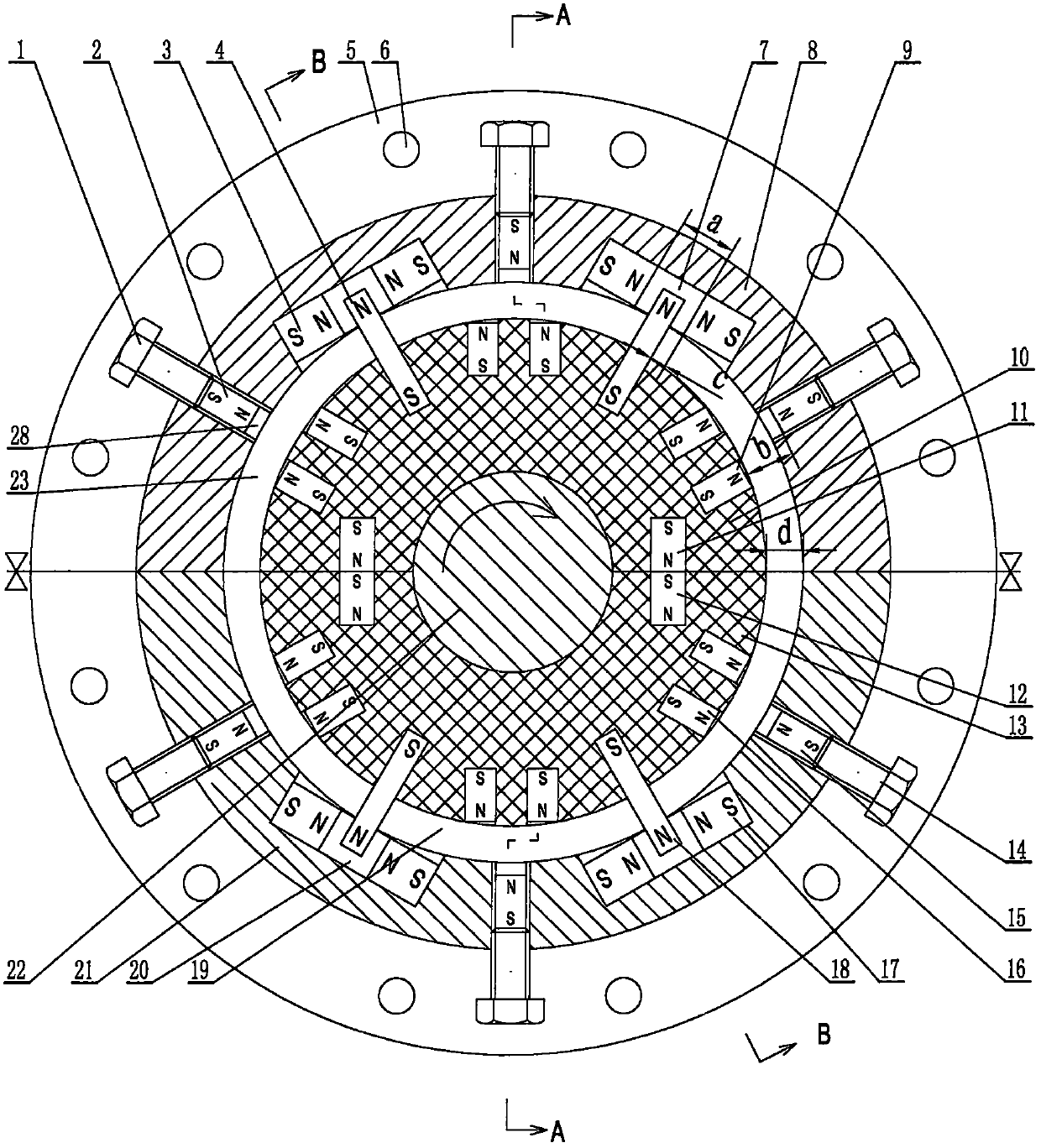
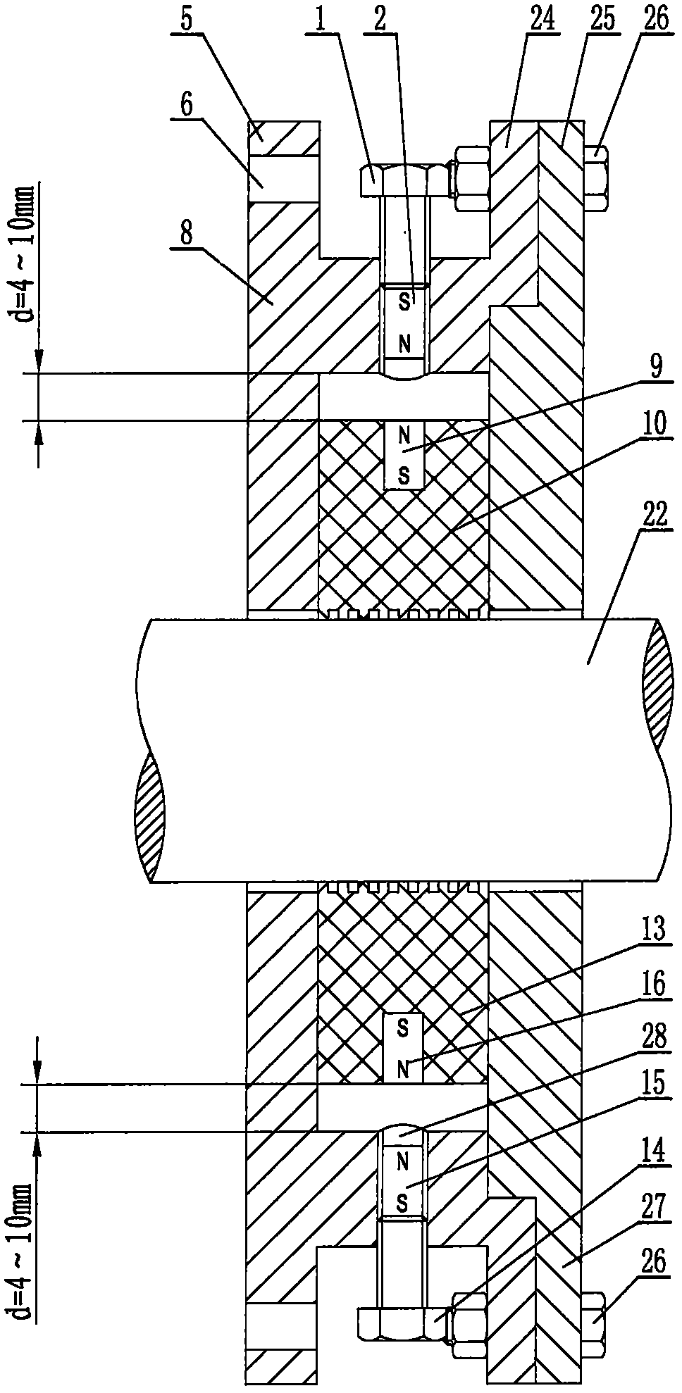
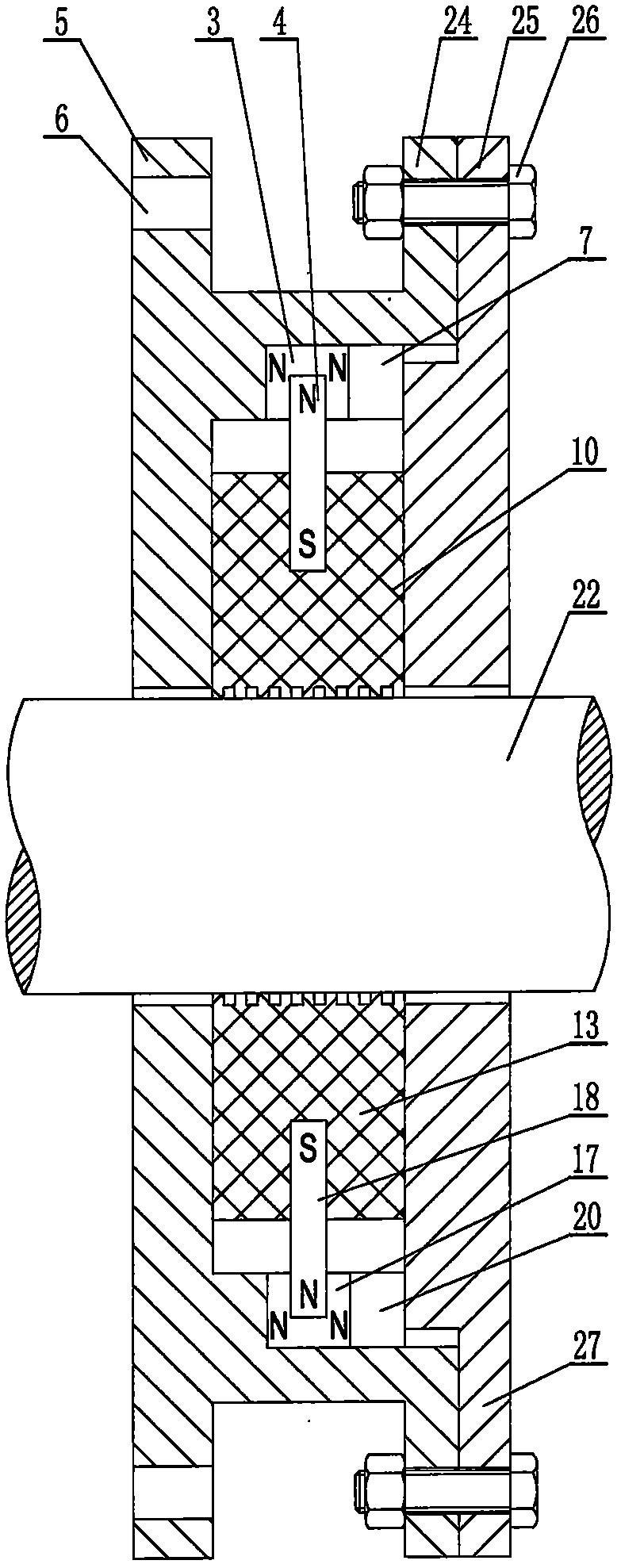
[0023] Screw the upper adjustment screws 1 with the upper adjustment magnetic columns 2 fixed at the front ends into the adjustment screw holes 28 evenly distributed on the upper valve seat ring 8, and the S poles of the upper adjustment magnetic columns 2 are fixed on the ends of the upper adjustment screws 1 . The inner magnetic blocks 3N poles of the paired upper limit are relatively fixed on both sides of the upper limit groove 7, and the surface distance of the two N poles is adjustable from 20 to 30 mm, and the upper limit groove 7 is symmetrically processed. Embed one or a pair of upper ring magnetic columns 9 corresponding to the position of the upper adjustment magnetic column 2 in parallel into the outer diameter of the upper floating seal ring 10, and the N poles of the upper ring magnetic columns 9 correspond to the N poles of the upper adjustment magnetic column 2; The S pole of the outer magnetic strip 4 of the upper ring is embedded in the outer diameter of the ...


PUM


Abstract

The invention discloses an adjustable magnetic levitation oil mist sealing device. Multiple upper and lower adjusting screws where upper and lower adjusting magnetic columns are fixed are arranged onan upper valve seat ring and a lower valve seat ring, upper limiting inner magnetic block and a lower limiting inner magnetic block which are in pairs and opposite in N pole are fixed in each upper limiting groove and each lower limiting groove symmetric with the upper limiting groove, and multiple or multiple pairs of upper and lower ring magnetic columns are embedded into the outer diameter of an upper floating seal ring and the outer diameter of a lower floating seal ring, wherein the N pole of the upper and lower ring magnetic columns is opposite to that of the upper and lower adjusting magnetic columns; upper and lower ring outer magnetic strips are embedded symmetrically respectively, the N poles are correspondingly placed into the centers of N pole regions of the upper and lower limiting inner magnetic blocks, the left ends and the right ends of the upper and lower floating seal rings are embedded into the upper and lower end magnetic columns with the S poles opposite to the N poles, an upper seal cover and a lower seal cover are fixed to an outer flange through connecting bolts, the upper valve seat ring and the lower valve seat ring are connected into a whole ring throughan upper cover connecting face and a lower cover connecting face, and the whole ring is fixed to a bearing end cover. The related technical scheme will certainly be widely used in the electric generator field and other related fields.

Description

Technical field: [0001] The invention relates to an oil mist sealing device for the bearing end cover of a generator. Background technique: [0002] At present, the oil mist seal device used in the vertical and horizontal bearing end covers of large generators basically adopts a hard packing floating seal structure. In order to prevent the floating seal ring formed by the floating seal body from rotating together with the large shaft, waist-shaped holes and screws are used to limit the position. , this limiting method makes it impossible for the entire floating seal ring to follow the large shaft to jump in the range of 360°, and even cause shaft grinding; each floating seal body is pre-tightened by a leaf spring so that it can move forward and backward when following the big shaft. It is easy to fail due to mechanical fatigue, and the floating sealing ring that loses its preload cannot follow the big shaft to beat, resulting in oil leakage. Therefore, there is an urgent ne...

Claims


Application Information

Patent Timeline
Patent Type & Authority Applications(China)
IPC IPC(8): F16J15/16H02K5/124
Inventor 吴雳鸣
Owner HARBIN SHENGDI ELECTRIC POWER EQUIP
Learn More