Corrugated tubular material with winding structure and strip material thereof

A corrugated and strip technology, applied in the direction of pipes, rigid pipes, pipes/pipe joints/fittings, etc., can solve the limited bearing capacity of hollow stiffeners, increase the force of the backfill layer on the hollow stiffeners, and the inner rib to enhance the outer corrugation. It can solve the problems such as subsidence of the wall pipe of the plastic wrapping structure, and achieve the effect of reducing the production process and improving the rigidity of the ring.

Inactive Publication Date: 2018-01-16
北京华宇中天环境工程有限公司
View PDF3 Cites 2 Cited by
  • Summary
  • Abstract
  • Description
  • Claims
  • Application Information

AI Technical Summary

Problems solved by technology

In actual use, the inner rib reinforced outer corrugated plastic winding structure wall pipe is covered with a backfill layer. In addition to its own gravity, the backfill layer often has heavy-duty vehicles passing by, which increases the force of the backfill layer on the hollow reinforcement. The hollow reinforcing rib has limited bearing capacity, so it will deform over time, causing the inner rib to reinforce the outer corrugated plastic winding structure wall pipe to sag

Method used


Image

  • Corrugated tubular material with winding structure and strip material thereof
  • Corrugated tubular material with winding structure and strip material thereof
  • Corrugated tubular material with winding structure and strip material thereof

Examples


Embodiment 1

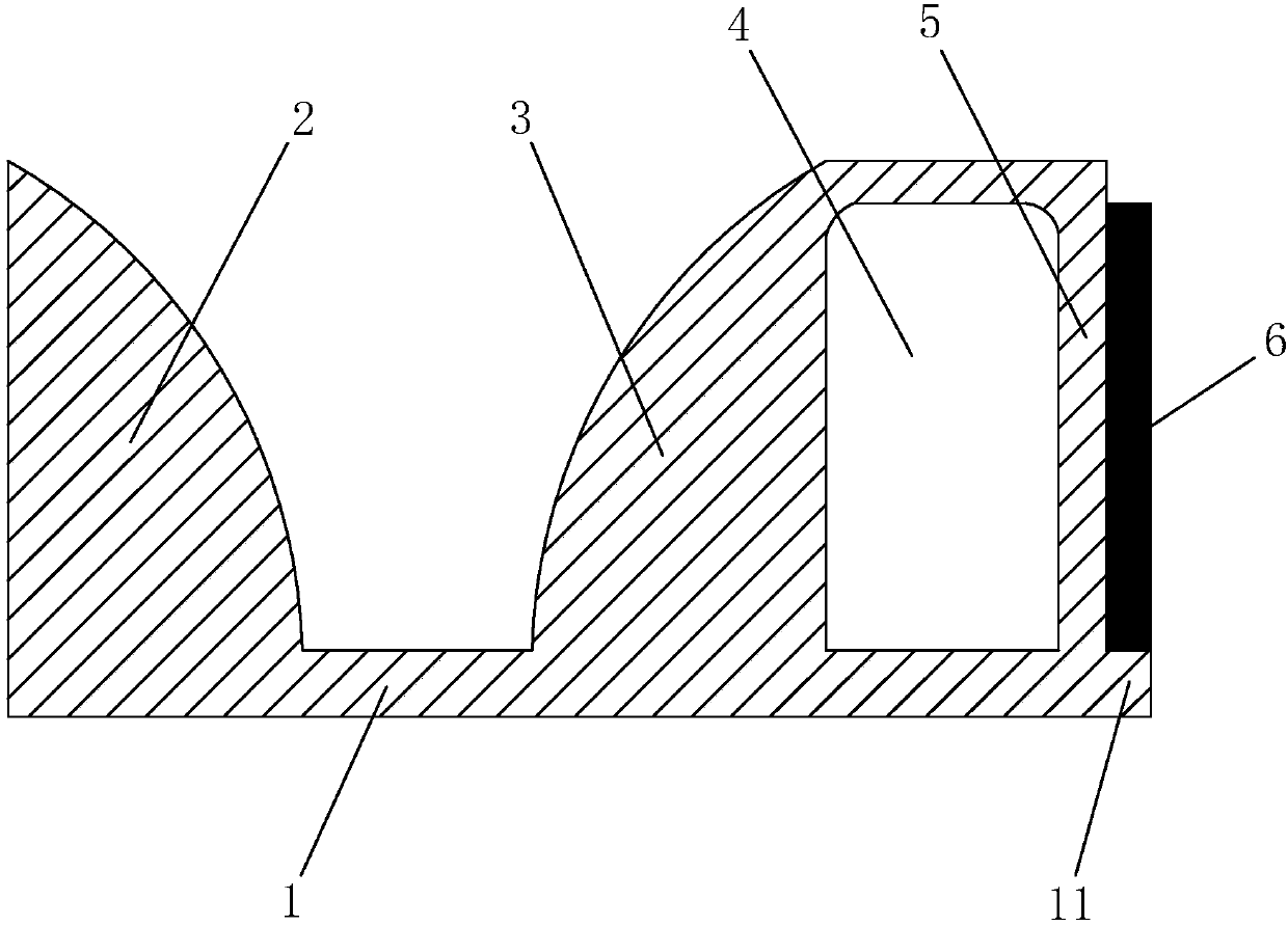
[0040] Embodiment one: a kind of tape, such as figure 1 As shown, including the negative film 1, the left solid convex part 2 and the right solid convex part 3 are integrally connected respectively on both sides of the negative film 1, the heights of the left solid convex part 2 and the right solid convex part 3 are the same, and the two opposite sides are Arc, and the side away from it is perpendicular to the negative film 1. The left end surface of the left solid convex part 2 is flush with the left end surface of the negative film 1, and the right end surface of the right solid convex part 3 is connected with a support rib 5 arranged perpendicular to the negative film 1. The bottom end of the support rib 5 is fixedly connected with the bottom sheet 1, and the top end of the support rib 5 extends to the top of the right solid convex part 3 and is fixedly connected. A cavity 4 is formed between the support rib 5 and the right solid convex portion 3 . The right end of the bo...

Embodiment 2

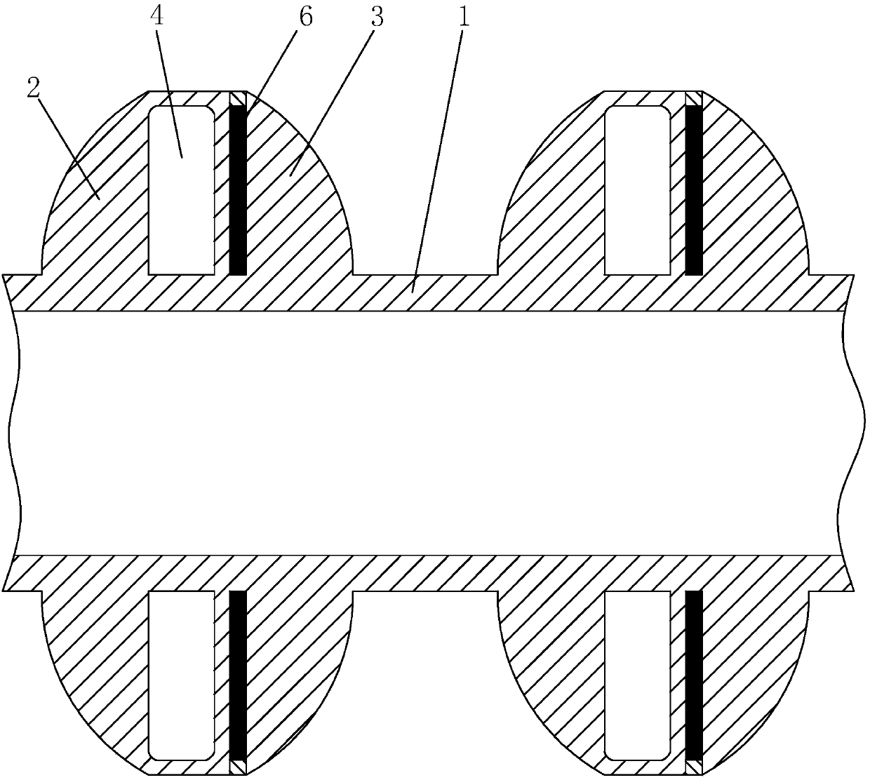
[0060] Embodiment two: a kind of tape, such as Figure 4 As shown, the difference from Example 1 is that the combination figure 1 , the same cavity 4 and support rib 5 are provided on the end face of the left solid convex part 2 . refer to Figure 5 and Figure 6 , the highest point of the corrugated pipe formed after the strip is wound is at the junction of the two supporting ribs 5, so that the surface ribs of the corrugated pipe form a solid-hollow-supporting rib 5+metal sheet 6-hollow-solid cycle structure, metal The sheet 6 increases the strength of the support rib 5 in the middle, increases its bearing capacity, and reduces the possibility of sagging in the middle. The connection area between the solid parts at both ends and the pipe wall is increased, which reduces the possibility of the connection being torn when the force is applied.

Embodiment 3

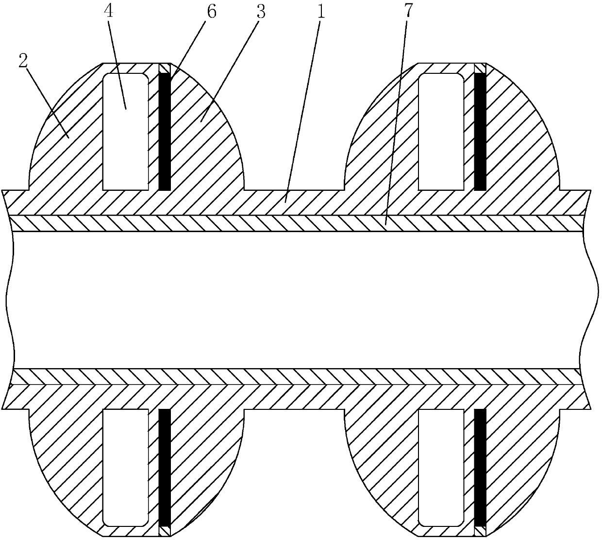
[0061] Embodiment three: a kind of tape, such as Figure 7 As shown, the difference from Example 2 is that the combination Figure 4 , the arc-shaped left solid convex portion 2 and the right solid convex portion are replaced with a trapezoidal convex portion 8 . refer to Figure 8 and Figure 9 Compared with the second embodiment, the advantage is that the top of the ribs on the surface of the bellows is flat, and the height of the supporting ribs 5 and metal sheets 6 in the middle is the same as that of the solid parts on both sides, which together play a supporting role and reduce the support in the middle Rib 5 and metal sheet 6 may be folded by external force.


PUM


Abstract

The invention discloses a corrugated tubular material with a winding structure and a strip material thereof. According to the technical scheme of the invention, the corrugated tubular material is characterized by comprising a bottom sheet, wherein a left solid protrusion is arranged on one side of the bottom sheet, a right solid protrusion is arranged on the other side of the bottom sheet, the right solid protrusion is connected with a supporting rib perpendicular to the bottom sheet, a cavity is defined by the supporting rib, the bottom sheet and the right solid protrusion, and the section, protruding out of the supporting rib, of the bottom sheet forms an extending portion. The problem is solved that an existing corrugated tube is insufficient in strength and accordingly collapse is likely to occur when the tube is used.

Description

technical field [0001] The present invention relates to pipes, and more particularly, to a corrugated wound structure pipe and strip thereof. Background technique [0002] Most of my country's urban rain and sewage systems were built in the 1950s, mainly using open channels and cement pipes. Since then, with the development of cities, most cities have remodeled and expanded the rain and sewage pipe systems, and adopted cement pipes, Pipes such as ductile cast iron pipes. When the corrugated plastic winding structure wall pipe appeared in the later period, it was widely used in the construction of municipal sewage pipelines because of its relatively good corrosion resistance and wear resistance. [0003] The corrugated plastic winding structure wall pipe will deform laterally when it is under the pressure of the backfill soil layer, and the force will be dispersed to the surrounding soil to form a joint force structure of the pipe and soil. The strength of the corrugated plas...

Claims


Application Information

Patent Timeline
Patent Type & Authority Applications(China)
IPC IPC(8): F16S3/00F16L9/16
Inventor 吴吕
Owner 北京华宇中天环境工程有限公司
Why Eureka
Try Eureka