Temperature detection method, detection device and terminal equipment of substation equipment

A technology for substation equipment and a detection method, which is applied in the field of computer-readable storage media and temperature detection of substation equipment, can solve problems such as inaccurate temperature detection results of substation equipment, and achieve the effect of improving accuracy and detection efficiency

Active Publication Date: 2019-07-23
国网江西省电力有限公司超高压分公司 +1
View PDF7 Cites 1 Cited by
  • Summary
  • Abstract
  • Description
  • Claims
  • Application Information

AI Technical Summary

Problems solved by technology

[0003] In the prior art, the staff uses a thermal imager to take a thermal imaging image of a certain surface of the substation equipment, and determines the temperature information of the surface of the substation equipment based on the thermal imaging image. However, since the substation equipment, especially some cylindrical equipment ( For example, circuit breakers, current transformers, lightning arresters, etc.) have a ring-shaped surface area, and the position where high temperature occurs may exist in a part of the surface area corresponding to any orientation. Thermal imaging images determine the temperature information on the surface of the substation equipment can only reflect the temperature of the corresponding part of the surface area of ​​the equipment, so the temperature detection results of the substation equipment are not accurate enough

Method used


Image

  • Temperature detection method, detection device and terminal equipment of substation equipment
  • Temperature detection method, detection device and terminal equipment of substation equipment
  • Temperature detection method, detection device and terminal equipment of substation equipment

Examples


Embodiment Construction

[0024] In the following description, specific details such as specific system structures and technologies are presented for the purpose of illustration rather than limitation, so as to thoroughly understand the embodiments of the present invention. It will be apparent, however, to one skilled in the art that the invention may be practiced in other embodiments without these specific details. In other instances, detailed descriptions of well-known systems, devices, circuits, and methods are omitted so as not to obscure the description of the present invention with unnecessary detail.

[0025] In order to illustrate the technical solutions of the present invention, specific examples are used below to illustrate.

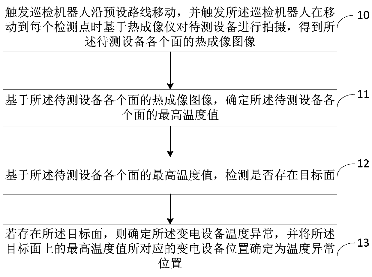
[0026] figure 1 The flow chart of the method for detecting the temperature of the substation equipment provided by the embodiment of the present invention is shown, and the details are as follows:

[0027] The embodiment of the present invention is applied to an inspe...


PUM


Abstract

The invention is suitable for the field of power equipment monitoring technology, and provides a detecting method, a detecting device, terminal equipment and a computer-readable storage medium for temperature of transformer equipment. The detecting method comprises the steps of triggering an inspection robot to move along a preset route, and triggering the inspection robot to perform photographingon the transformer equipment based on a thermal imaging instrument when the inspection robot moves to each detecting point, obtaining the thermal image of each surface of the transformer equipment, and furthermore determining the highest temperature of each surface of the transformer equipment; detecting whether a target surface exists based on the highest temperature of each surface of the transformer equipment; and if the target surface exists, determining temperature abnormity of the transformer equipment, and determining the transformer equipment position which corresponds with the highest temperature on the target surface as a temperature abnormal position. The detecting method, the detecting device, the terminal equipment and the computer-readable storage medium have advantages of realizing omnibearing temperature detection on the surface of the transformer equipment, improving detecting efficiency and detecting result accuracy.

Description

technical field [0001] The invention belongs to the technical field of electric power equipment monitoring, and in particular relates to a detection method, a detection device, a terminal device and a computer-readable storage medium for the temperature of a substation equipment. Background technique [0002] In the power system, when inspecting and maintaining substations, detecting the temperature of the substation equipment is an indispensable part of the inspection. For example, when a part of the substation fails, the temperature of the corresponding surface area of ​​the part will Therefore, in the inspection, it is necessary to detect whether the substation equipment is abnormal by detecting the temperature information on the surface of the substation equipment. [0003] In the prior art, the staff uses a thermal imager to take a thermal imaging image of a certain surface of the substation equipment, and determines the temperature information of the surface of the sub...

Claims


Application Information

Patent Timeline
Patent Type & Authority Patents(China)
IPC IPC(8): G01J5/00
Inventor 叶爱民胡宏宇徐波王金生张立群彭志远谷湘煜任春勇鲜开义周仁彬张健杨莉君樊波
Owner 国网江西省电力有限公司超高压分公司
Why Eureka
Try Eureka