Optical sensing line external breakage monitoring device

A monitoring device and sensing line technology, applied in the direction of the fault location, etc., can solve the problems of high labor intensity, high cost of single equipment, line failure, etc. The effect of work intensity

Inactive Publication Date: 2018-01-16
武汉伊莱维特电力科技有限公司
View PDF1 Cites 4 Cited by
  • Summary
  • Abstract
  • Description
  • Claims
  • Application Information

AI Technical Summary

Problems solved by technology

However, this method has disadvantages such as long line inspection cycle, high labor intensity, and difficulty in finding hidden dangers in time.
[0004] In this context, video online monitoring technology has been applied in power grids across the country since 2007. Although video monitoring is a mature technology, the following problems generally exist: (1) The on-duty personnel are required to be on duty uninterruptedly. Look at the computer screen to find out whether possible external force damage factors can be seen in the returned video or photos. The frequency of reference in actual work is extremely low, which makes it impossible to detect external force damage in time. By the time the external force damage is found, it has already occurred Line faults have limited guiding significance for the work of anti-breakage and tripping of lines
(2) Traditional video surveillance devices are equipped with only one camera, and most of them can only shoot live images in one direction. Some cameras equipped with rotating pan-tilts are limited by power supply and operational reliability, and the actual use effect is not good.
(3) The cost of a single device is too high, and there are many line sections that need to be monitored, resulting in many monitoring blind spots

Method used


Image

  • Optical sensing line external breakage monitoring device
  • Optical sensing line external breakage monitoring device

Examples


Embodiment Construction

[0028] In order to make the technical means, creative features, goals and effects achieved by the present invention easy to understand, the present invention will be further described below in conjunction with specific embodiments.

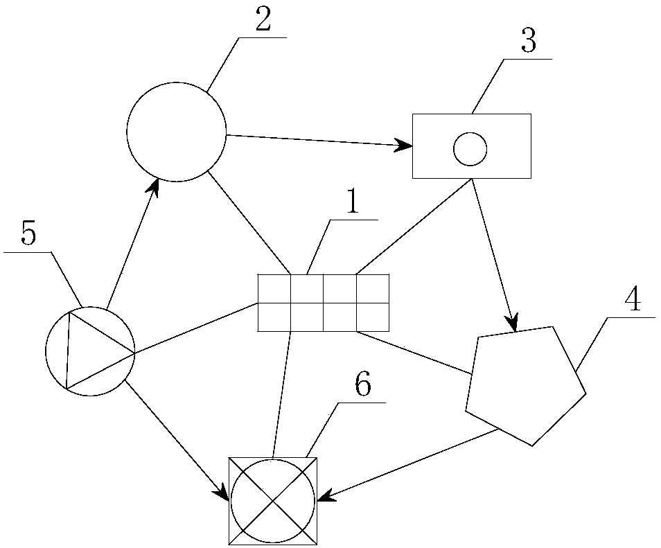
[0029] see figure 1 with figure 2 , the present invention provides a technical solution: a monitoring device for a broken optical sensing line, the monitoring device includes: a power supply device 1, a distributed optical fiber sensing system 2, an optical signal acquisition system 3, and a data acquisition and processing system 4. Visual monitoring device 5 and indoor monitoring equipment 6;

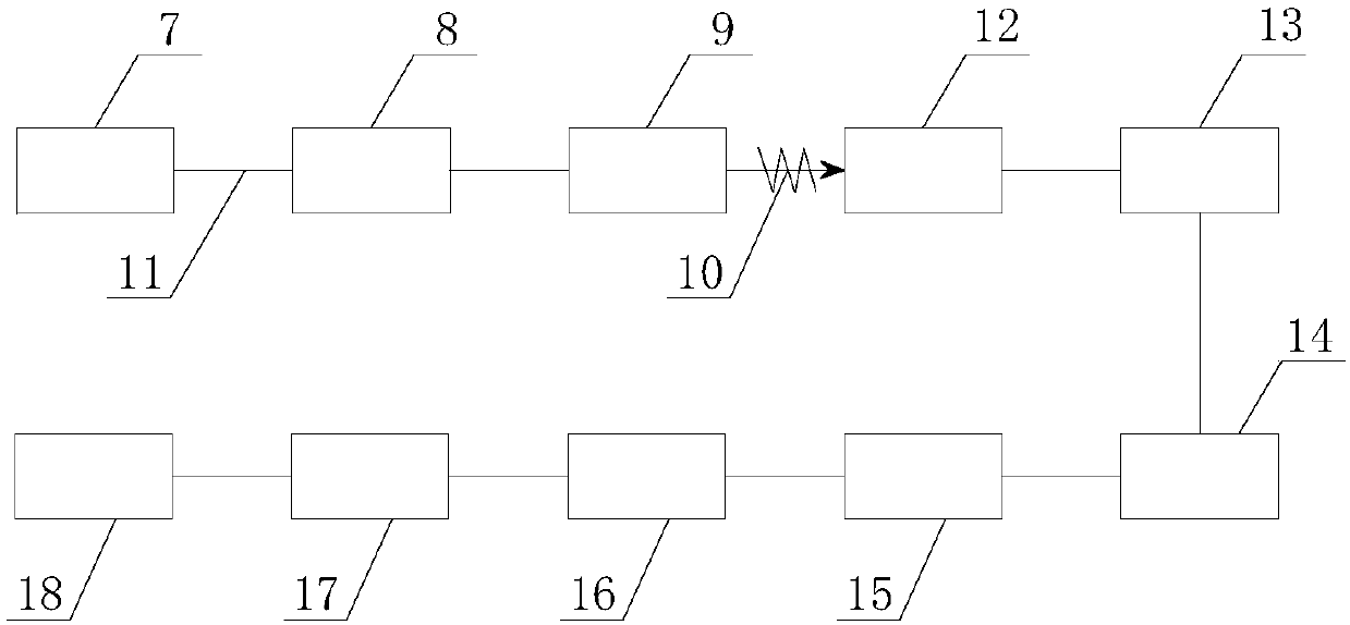
[0030] The distributed optical fiber sensing system 2 is composed of a pulsed laser light source 7, an optical isolator 8, a coupler 9, a delay optical fiber 10 and a sensing optical fiber 11;

[0031] The optical signal acquisition system 3 is composed of a photodetector 12 and a photoelectric converter 13;

[0032] Described data acquisition and proc...


PUM


Abstract

The present invention relates to an optical sensing line external breakage monitoring device. The monitoring device comprises a power supply device, a distributed optical fiber sensing system, an optical signal acquisition system, a data acquiring and processing system, a visual monitoring device and an indoor monitoring device. The distributed optical fiber sensing system is composed of a pulse laser source, an optical isolator, a coupler, a delay optical fiber and a sensing optical fiber, the optical signal acquisition system is composed of a photoelectric detector and a photoelectric converter, and the data acquiring and processing system is composed of a high-speed data acquisition card, a data storage device and a computer. The optical sensing line external breakage monitoring deviceof the present invention utilizes the optical fibers as the sensors, so that the line external breakage abnormity vibration monitoring is realized, and a monitoring terminal can be triggered to photograph and obtain the evidences real-timely. The line external breakage monitoring device of the present invention enables the line external breakage patrol inspection working intensity to be reduced greatly, the working quality to be improved, and the technological level and the management level of the line external breakage prevention field to be improved more substantially.

Description

technical field [0001] The invention belongs to the technical field of power transmission line state monitoring equipment, and in particular relates to a monitoring device for an optical sensing line breakage. Background technique [0002] In recent years, as users have higher and higher requirements for power supply reliability, transmission line maintenance has increasingly become one of the mainstream tasks of power supply departments. However, external force damage is the biggest hidden danger affecting the safety of transmission lines. Due to the characteristics of large areas, many points, long lines, and long-term exposure to the wild, transmission lines are more vulnerable to damage. In addition, in recent years, urbanization construction, infrastructure construction, quarrying Human activities such as mining, logging, and road construction are becoming more and more frequent, resulting in repeated damage to transmission lines caused by external force damage, and the...

Claims


Application Information

Patent Timeline
Patent Type & Authority Applications(China)
IPC IPC(8): G01R31/08
Inventor 刘伟郑晨
Owner 武汉伊莱维特电力科技有限公司
Why Eureka
Try Eureka