
An Integral Measurement Method of Pipeline Vibration Response

A technology of vibration response and overall measurement, which is applied in the direction of measuring devices, measuring ultrasonic/sonic/infrasonic waves, CAD based on constraints, etc. It can solve the problems of unable to measure the vibration of measuring points, manpower, material and financial resources consumption, and no space for installing acceleration sensors. Conditions and other issues, to achieve the effect of solving the difficulty of vibration response data measurement and simple operation

Active Publication Date: 2020-12-01
NO 719 RES INST CHINA SHIPBUILDING IND
View PDF3 Cites 0 Cited by
  • Summary
  • Abstract
  • Description
  • Claims
  • Application Information

AI Technical Summary

Problems solved by technology

But for large-scale pipeline systems, when there are many vibration locations that need to be paid attention to, it is necessary to set more measuring points on the pipeline and use a large number of acceleration sensors, resulting in a large consumption of manpower, material and financial resources, and Due to the complex structure and position characteristics of the pipeline system, some measuring points do not have the space conditions for installing acceleration sensors, or the test environment at the location of the measuring points is harsh, which is not suitable for long-term work, resulting in the inability to measure the vibration of these key measuring points

Method used


Image

  • An Integral Measurement Method of Pipeline Vibration Response
  • An Integral Measurement Method of Pipeline Vibration Response
  • An Integral Measurement Method of Pipeline Vibration Response

Examples


Embodiment Construction

[0025] The present invention will be described in further detail below in conjunction with the accompanying drawings.

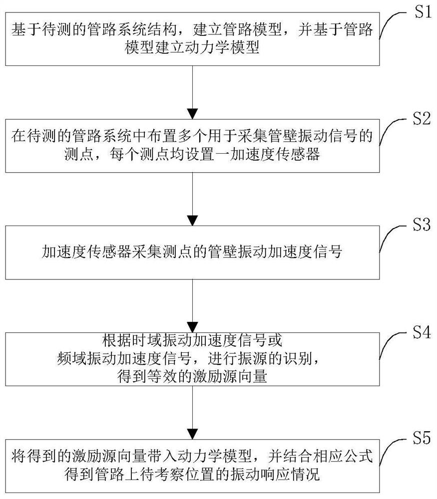
[0026] see figure 1 As shown, the present invention provides an overall measurement method for pipeline vibration response, by measuring the vibration response of a small number of measuring points in the pipeline system, and according to the measured data, the vibration response of any point in the entire pipeline system can be accurately measured. Prediction, the overall measurement method of pipeline vibration response of the present invention specifically includes:

[0027] S1: Based on the pipeline system structure to be tested, establish a pipeline model, and establish a dynamic model based on the pipeline model:

[0028] Φ start =UΦ end +Q(F,U,D) (1)

[0029] Among them, Φ start Denotes the state vector at the beginning of the pipeline, Φ end Represents the state vector at the end of the pipeline, U represents the transfer matrix between the end ...


PUM


Abstract

The invention discloses an overall measurement method of pipeline vibration response, and relates to the field of engineering measurement. The method comprises the following steps: S1, establishing apipe model based on a pipeline system structure to be measured, and establishing a dynamic model based on the pipeline model; S2, arranging a plurality of measuring points for acquiring pipe wall vibration signals in a pipeline system to be measured; S3, acquiring pipe wall vibration acceleration signals of the measuring points through an acceleration sensor, and meanwhile converting an acquired time domain vibration acceleration signal into a frequency domain vibration acceleration signal through Fourier transform; S4, determining the position and size of an equivalent excitation source in the pipeline system according to the time domain vibration acceleration signal or the frequency domain vibration acceleration signal to obtain an equivalent excitation source vector; and S5, bringing the obtained excitation source vector into the dynamic model, and getting the vibration response situation of a position to be inspected on the pipeline in conjunction with a formula. Through adoption of the method, the vibration response situation of any point on the whole pipeline is accurately predicted through vibration measurement of a few measuring points.

Description

technical field [0001] The invention relates to the field of engineering measurement, in particular to an overall measurement method for pipeline vibration response. Background technique [0002] Fluid pipelines are widely used in ships and ocean engineering, energy and power industry, petrochemical industry, aircraft power system and daily life. While the pipeline system transports the fluid, the vibration energy will be transmitted to the pipeline along the pipe wall and the fluid in the pipe. Each position of the pipeline system will cause damage to the pipeline and other components connected to the pipeline and precision instruments, affect the safety of the pipeline system and the normal operation of the pipeline power system, and even cause huge economic losses in severe cases. Therefore, the pipeline The vibration test of the pipeline system has become an important link in the design process of the pipeline system. [0003] The common method of pipeline vibration mea...

Claims


Application Information

Patent Timeline
Patent Type & Authority Patents(China)
IPC IPC(8): G06F30/20G01H17/00G06F17/14G06F17/16G06F113/14G06F119/14G06F111/04
Inventor 李帅军沈石头刘少有吴淏刘修良余志庭李俊益
Owner NO 719 RES INST CHINA SHIPBUILDING IND
Learn More