A rail transit full line simulation system and simulation method

A line simulation and rail transit technology, applied in the field of rail transit, can solve problems such as the inability to give the DC voltage change trend of the entire line, the high system complexity of the energy feedback device, and the waste of capacity configuration, so as to achieve real and reliable simulation results and improve The effect of feedback efficiency and simple method

Active Publication Date: 2020-12-18
NR ELECTRIC CO LTD +1
View PDF5 Cites 0 Cited by
  • Summary
  • Abstract
  • Description
  • Claims
  • Application Information

AI Technical Summary

Problems solved by technology

When designing the system, it is necessary to calculate the configuration capacity of the energy feedback device, that is, whether the maximum feedback current can meet the requirements. If the capacity configuration is too high, it will cause waste. If the configuration is too low, the DC bus voltage will be too high, and the equipment on the DC traction network will be damaged due to overvoltage. Therefore, it is necessary to check the configuration capacity of the regenerative energy feedback device in the traction station
[0003] The entire DC traction line contains multiple traction stations, and the line equivalent resistance is included between each traction station. During the operation of the locomotive, the position and speed of the locomotive are different, so that the various parameters are coupled together, which is difficult to calculate. The energy feedback device The introduction makes the system more complex, it is difficult to calculate the configuration capacity through theoretical calculations, and the change trend of the DC voltage of the entire line cannot be given, and there is currently no solution to meet the above requirements. It is proposed to build a full line simulation system, including the main equipment of the entire line, which can verify the capacity configuration of energy feedback equipment

Method used


Image

  • A rail transit full line simulation system and simulation method

Examples


Embodiment Construction

[0028] The implementation process of the present invention will be described in detail below in conjunction with the accompanying drawings.

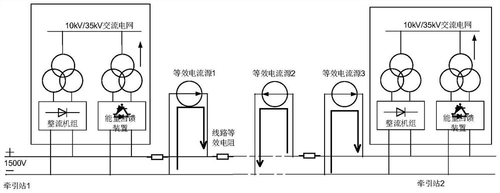
[0029] A rail transit full line simulation system, the simulation system includes a rail traffic direct current line, the direct current line is connected to at least one traction station, and the traction station contains line equivalent resistance. In this implementation, the present invention is applied to the track The DC traction line of the subway for transportation has a DC voltage rating of 1500V. In this embodiment, N traction stations are included, and N=2. The equivalent resistance of the line is included between the two traction stations. In this embodiment, it is divided into two according to the line parameters. Each traction station includes a rectifier unit and an AC power grid, and the traction station also includes an energy feedback device.

[0030] The simulation system of this embodiment also includes three equivalen...


PUM


Abstract

The invention discloses a rail traffic full-circuit simulation system. The simulation system comprises a rail traffic direct-current circuit, the circuit is connected with at least one traction substation, the traction substations include circuit equivalent resistors and are internally provided with rectifier units, energy feedback devices and alternating current power grids, the simulation systemfurther comprises at least at least one equivalent current source, the current numerical value of the equivalent current source is decided by the state of a motor vehicle running on the direct-current circuit, and calculation is automatically conducted according to the position, the weight, the running direction and the running speed of the motor vehicle. An equivalent current supply simulates the energy for braking and starting the motor vehicle, an energy feedback device is arranged in each traction substation, analogue simulation of the condition of voltage and current of the whole circuitcan be achieved, and whether allocated capacities for the energy feedback devices can meet the requirement or not is verified.

Description

technical field [0001] The invention is applied to the rail transit field, and in particular relates to a full-line simulation system applied to the rail transit. Background technique [0002] There is a demand for regenerative energy utilization in the field of rail transit. When the locomotive is running, the braking energy will be fed back to the traction network, and it will be absorbed and utilized by adjacent vehicles first. When the generated regenerative energy cannot be used by adjacent vehicles , the train braking will continue to raise the voltage of the DC traction network. When the setting value of the energy feedback device installed in the substation is reached, the device will be switched on and start to absorb regenerative electric energy. When designing the system, it is necessary to calculate the configuration capacity of the energy feedback device, that is, whether the maximum feedback current can meet the requirements. If the capacity configuration is to...

Claims


Application Information

Patent Timeline
Patent Type & Authority Patents(China)
IPC IPC(8): G06F30/20
Inventor 谢晔源刘洪德王宇杨浩连建阳
Owner NR ELECTRIC CO LTD
Why Eureka
Try Eureka