Electroluminescent element driving circuit, driving method thereof and display device

A technology of electroluminescent elements and driving circuits, which is applied in static indicators, instruments, etc., can solve the problems of the limitation of the brightness adjustment range of electroluminescent elements and affect the wide application of electroluminescent display panels, etc., so as to increase the brightness adjustment range , increase the range of changes, and expand the effect of the scope of application scenarios

Inactive Publication Date: 2018-01-16
BOE TECH GRP CO LTD
View PDF7 Cites 29 Cited by
  • Summary
  • Abstract
  • Description
  • Claims
  • Application Information

AI Technical Summary

Problems solved by technology

[0003] In the manufacture of silicon-based electroluminescent display panels, due to the limitation of the manufacturing process (that is, the manufacturing process), the data range (data voltage range) transmitted to the electroluminescent element (that is, the pixel) will be limited to a certain extent, resulting in the electroluminescent element The brightness adjustment range of the electroluminescent element will be limited to a certain extent, that is, the brightness adjustment range of the electroluminescent element will be limited to a small range, and the limited brightness adjustment range will limit the application scenarios of the silicon-based electroluminescent display panel to a limited range. range, seriously affecting the wide application of electroluminescent display panels

Method used


Image

  • Electroluminescent element driving circuit, driving method thereof and display device
  • Electroluminescent element driving circuit, driving method thereof and display device
  • Electroluminescent element driving circuit, driving method thereof and display device

Examples


Embodiment 1

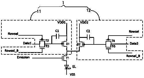
[0035] This embodiment provides a driving circuit for an electroluminescent element, such as figure 1 As shown, it includes the first switching tube T1 and at least two driving circuit units 1, the driving circuit units 1 are connected in parallel, and the driving circuit unit 1 is connected to the first pole of the first switching tube T1, and the first switching tube T1 The gate is connected to the lighting control signal Emission, the second pole of the first switch tube T1 is connected to the anode of the electroluminescent element EL, and the cathode of the electroluminescent element EL is connected to the first potential terminal VSS; the driving circuit unit 1 is used to write The data signal Data drives the electroluminescence element EL to emit light.

[0036] In this embodiment, the electroluminescent element EL is an organic electroluminescent element. It should be noted that the electroluminescent element may also be an inorganic electroluminescent element.

[00...

Embodiment 2

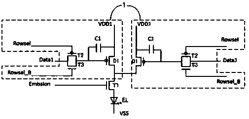
[0049] This embodiment provides a driving circuit for an electroluminescent element, which is different from that in Embodiment 1, such as Figure 4 As shown, the circuits of each driving circuit unit 1 are the same; each driving circuit unit 1 includes a second switching tube T2, a third switching tube T3, a first capacitor C1 and a first driving tube D1. The gate of the second switching tube T2 is connected to the first charging control signal Rowsel, the gate of the third switching tube T3 is connected to the second charging control signal Rowsel_B, the first electrode of the second switching tube T2 and the first electrode of the third switching tube T3 The pole is connected to the first data signal Data1, the second pole of the second switching tube T2 and the second pole of the third switching tube T3 are connected to the gate of the first driving tube D1 and the first pole of the first capacitor C1; the first capacitor C1 The second pole of the first driving transistor ...

Embodiment 3

[0055] This embodiment provides a display device, including the driving circuit in Embodiment 1 or 2.

[0056] By adopting the driving circuit in Embodiment 1 or 2, the brightness adjustment range of the display device can be increased, thereby expanding the scope of application scenarios of the display device.

[0057] The display device provided by the present invention can be any product or component with a display function such as an organic electroluminescence panel, an organic electroluminescence television, an inorganic electroluminescence panel, an inorganic electroluminescence television, a display, a mobile phone, or a navigator.


PUM


Abstract

The invention provides an electroluminescent element driving circuit, a driving method thereof and a display device. The electroluminescent element driving circuit comprises a first switch tube and ischaracterized by further comprising at least two driving circuit units, wherein the driving circuit units are mutually connected in parallel, the driving circuit units are connected with a first electrode of the first switch tube, a grid electrode of the first switch tube is connected with a turn-on control signal, a second electrode of the first switch tube is connected with an anode of an electroluminescent element, and a cathode of the electroluminescent element is connected with a first potential terminal; and the driving circuit units are used for driving the electroluminescent element to emit light according to a write-in data signal. The driving circuit can realize simultaneous and concurrent driving of the at least two driving circuit units for the electroluminescent element, thereby increasing the variation range of driving current of the electroluminescent element, thus increasing the brightness adjustment range of the electroluminescent element, and expanding the application scenario range of an organic electroluminescent display product adopting the driving circuit.

Description

technical field [0001] The present invention relates to the field of display technology, in particular to a driving circuit and a driving method of an electroluminescence element, and a display device. Background technique [0002] The electroluminescence display panel includes an organic electroluminescence (Organic Light-Emitting Diode, OLED) display panel and an inorganic electroluminescence (MicroLED) display panel. At present, with the vigorous development of display technology, the electroluminescent display panel has become the trend of the display panel industry in the future due to its high contrast ratio and low power consumption. [0003] In the manufacture of silicon-based electroluminescent display panels, due to the limitation of the manufacturing process (that is, the manufacturing process), the data range (data voltage range) transmitted to the electroluminescent element (that is, the pixel) will be limited to a certain extent, resulting in the electrolumines...

Claims


Application Information

Patent Timeline
Patent Type & Authority Applications(China)
IPC IPC(8): G09G3/3208G09G3/32
Inventor 岳晗陈小川玄明花杨盛际杨明王灿张粲
Owner BOE TECH GRP CO LTD
Why Eureka
Try Eureka