Voting method based on dual-channel voting system

A voting system and dual-channel technology, which is applied in the voting field based on the dual-channel voting system, can solve problems that are prone to errors, affect the normal process of the meeting, and human errors, so as to avoid human errors, eliminate single-point failures, and simple control logic Effect

Active Publication Date: 2018-01-16
CHENGDU CAS INFORMATION TECH CO LTD
View PDF8 Cites 9 Cited by
  • Summary
  • Abstract
  • Description
  • Claims
  • Application Information

AI Technical Summary

Problems solved by technology

This solution can solve the situation that the meeting cannot be continuously guaranteed when the main voting system fails. However, there are two problems in the actual operation process. One is that the participants need to switch to the virtual keys on the touch screen after the standby system is activated. Proposal voting is carried out on the computer, rather than on the physical buttons under normal circumstances. This must be explained by the meeting host during the meeting. If the main system is faulty during the voting process, then There is also a need for a re-vote on a resolution that has already been voted on, which also requires special clarification
In short, the host's special instructions will greatly affect the normal process of the meeting and bring great difficulties to the organization of the meeting; on the other hand, this kind of system-level switching is also operated by the operator. There is also the possibility of human error, and the participants are also prone to make mistakes when voting, for example, they do not vote on the virtual buttons, but still vote on the main voting device

Method used


Image

  • Voting method based on dual-channel voting system
  • Voting method based on dual-channel voting system

Examples


Embodiment Construction

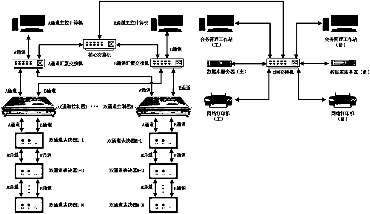
[0030]A voting system based on dual-core and dual-link, which adopts the architecture design of dual-link real-time hot backup for the whole system. Such as figure 1 As shown, it includes A and B channel main control computers, A and B channel convergence switches and at least one dual-channel controller, and the dual-channel controller is connected with several dual-channel voting devices connected hand in hand; the A channel main Control computer, A channel aggregation switch, A channel of dual-channel controller, and A channels of several dual-channel voting devices connected hand in hand are connected in turn to form voting link A; said B channel main control computer, B channel aggregation switch, The B channel of the dual-channel controller and the B channels of several dual-channel voting devices connected hand in hand are sequentially connected to form a voting link B independent of the voting link A.

[0031] Both the A-channel aggregation switch and the B-channel ag...


PUM


Abstract

The invention discloses a voting method based on a dual-channel voting system. When voting starts, an A channel main control computer sends a voting starting command to a B channel main control computer; the A channel main control computer and the B channel main control computer send the voting command to corresponding channels of dual-channel controllers to be in a voting state, and the dual-channel controllers collect key information and send the key information to the main control computers; the A channel main control computer and the B channel main control computer receive voting data sentby the respective channels and forward the received voting data to each other; the A channel main control computer and the B channel main control computer process the voting data of the two channelsrespectively, merge the processed data and count and display the merged data; and when voting terminates, the A channel main control computer sends a voting terminating command to the B channel main control computer, then the A channel main control computer and the B channel main control computer sends the voting terminating command to the corresponding channels of the dual-channel controllers, and voting is finished. According to the voting method, two real-time on-line complete voting links which backup each other are formed, area isolation is achieved on the premise of forming systems separately, common network attacks can be defended, and the robustness and the stability of an overall network system are enhanced.

Description

technical field [0001] The invention relates to a voting method based on a dual-channel voting system. Background technique [0002] The way of meeting voting has gone through the evolution process from clapping, raising hands to using electronic voting system. [0003] The usual manifestation of the electronic voting system is to set up a secret ballot device in front of each representative, with three buttons "for, against, and abstention" on it. After the representative presses the button, the data of each electronic voting device in the venue will be controlled by voting. The results are summarized and forwarded to the main control computer. After the main control computer counts the results, it displays the voting results on the electronic screen in the venue. [0004] Generally speaking, the architecture of the voting system basically adopts the form of "voting device-voting controller-master computer". The voting units in the venue are connected hand in hand and the...

Claims


Application Information

Patent Timeline
Patent Type & Authority Applications(China)
IPC IPC(8): H04L1/22H04L12/24G07C13/00
Inventor 彭程史志明官磊李国勇唐小平黎发明
Owner CHENGDU CAS INFORMATION TECH CO LTD
Why Eureka
Try Eureka