
Supporting structure for selective laser melting forming and generating method thereof

A support structure, laser melting technology, applied in the direction of process efficiency improvement, processing and manufacturing, solid material additive processing, etc., can solve the problems of increased post-processing difficulty, powder cannot be removed, material waste, etc., to shorten the forming time, reduce Post-processing difficulty and cost reduction effect

Active Publication Date: 2018-01-19
西安国宏天易智能科技有限公司
View PDF8 Cites 7 Cited by
  • Summary
  • Abstract
  • Description
  • Claims
  • Application Information

AI Technical Summary

Problems solved by technology

It is molded at the same time as the parts, connected up and down or with the parts, or connected with the substrate. After the forming is completed, the powder in the grid cannot be removed, resulting in waste of materials and increased costs. After heat treatment, the powder and the grid support are fused together, increasing the cost. post-processing difficulty

Method used


Image

  • Supporting structure for selective laser melting forming and generating method thereof
  • Supporting structure for selective laser melting forming and generating method thereof
  • Supporting structure for selective laser melting forming and generating method thereof

Examples


Embodiment Construction

[0029] The present invention will be further described in detail below in conjunction with specific embodiments, which are explanations of the present invention rather than limitations.

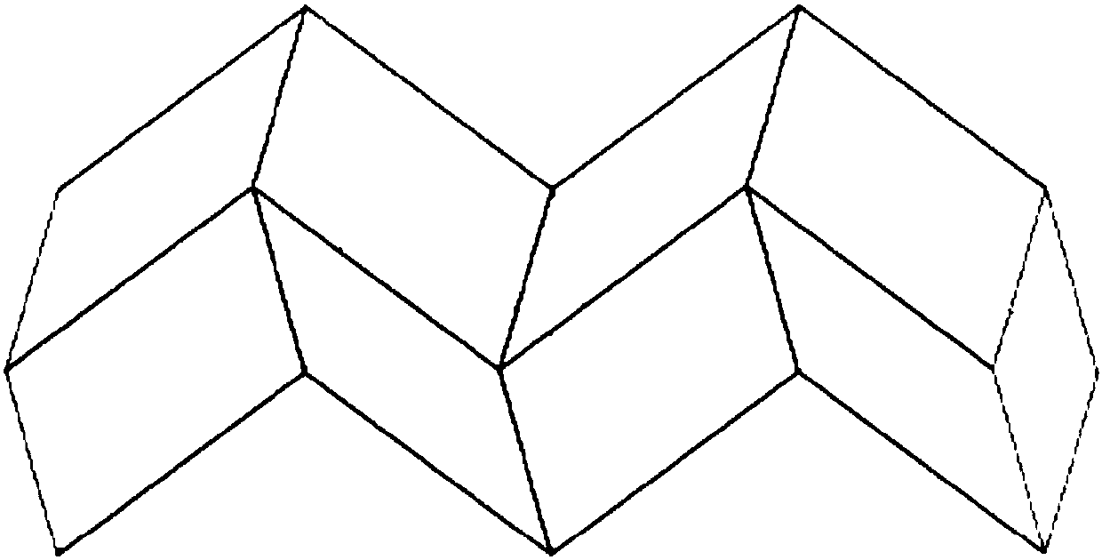
[0030] The supporting structure of the present invention, such as image 3 , Figure 4 , Figure 5 , Image 6 and Figure 7 As shown, it includes several support units 1 arranged in an array on the same plane; each support unit 1 includes several support units 2, and the support units 2 are empty tube structures arranged in the horizontal direction, with the length of the empty tube The direction is the X direction, and several support units 2 are arranged in an array in the Y direction and the Z direction. The adjacent support units 1 are connected to each other through the empty pipe wall to form the support unit 1, and the empty pipe forms the lateral outlet of the support unit 1. powder channel. Empty pipe can be set to broken line shape, and the direction of broken line can be set t...


PUM


Abstract

The invention relates to a supporting structure for selective laser melting forming and a generating method of the supporting structure. The supporting structure is simple in structure, and the loss of raw materials is reduced in the production process, the printing efficiency is improved, and the post-processing difficulty is reduced. The supporting structure comprises a plurality of supporting units which are arranged on the same plane in an array mode; each supporting unit comprises a plurality of supporting single bodies, the supporting single bodies are of hollow tube structures which arearranged in the horizontal direction, the length direction of the hollow tubes is taken an X direction, the plurality of supporting single bodies are arranged in an array mode in a Y direction and aZ direction, every adjacent supporting units are mutually connected through walls of hollow tubes to form the supporting units; and the hollow tubes form lateral powder discharging channels of the supporting units. According to the generating method, a cross section structure is formed by utilizing three-dimensional graphic software, array and arrangement are carried out for the area required to be supported according to requirements, the use requirements are met, and the supporting structure together with the part data can be output and completed to be formed synchronously; and in the settingand forming process, the the supporting units are directly reinforced for guaranteeing of the supporting effect.

Description

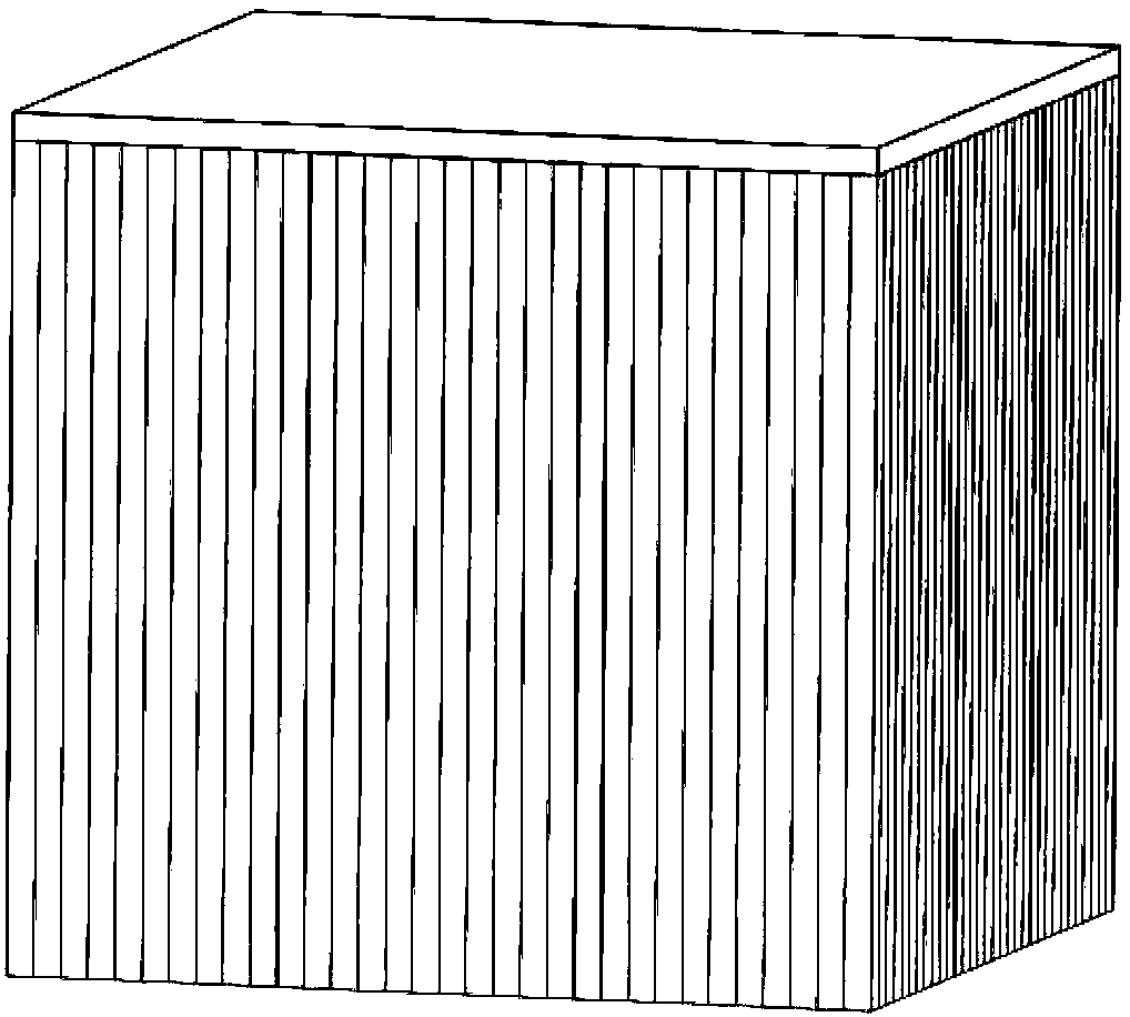
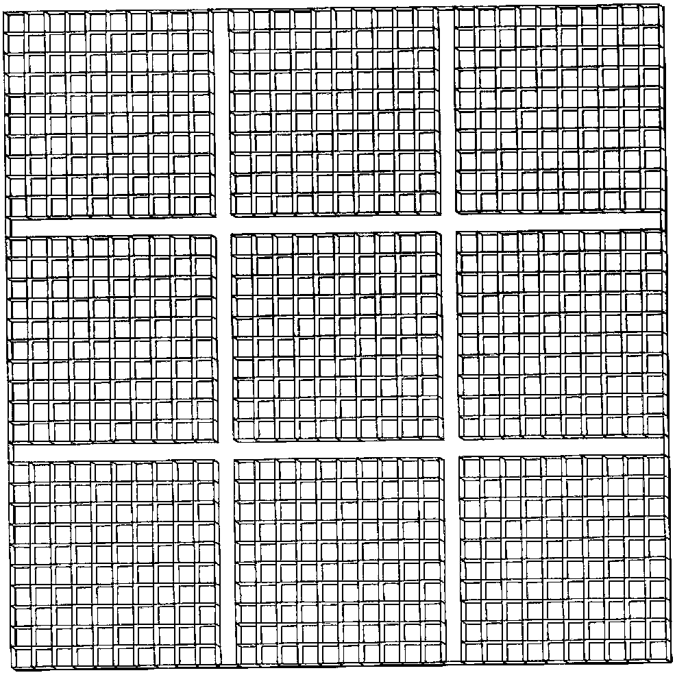
technical field [0001] The invention relates to a support in selective laser melting forming technology, in particular to a support structure for selective laser melting forming and a generating method thereof. Background technique [0002] Selective laser melting forming technology is a rapid additive manufacturing forming technology. It adopts laser heat source, accumulates layer by layer after powder coating, and quickly realizes the near-net shape of high-complexity parts. The forming method based on its layer-by-layer accumulation needs to add grid support to its suspended surfaces, edges, points and features that cannot be self-supported to ensure the smooth forming of the parts, while achieving the required surface roughness and dimensional accuracy. [0003] Existing mesh supports such as figure 1 with figure 2 As shown in the figure, the grid support form included in the software is added for support, which is a vertical grid, and only the size of a single grid u...

Claims


Application Information

Patent Timeline
Patent Type & Authority Applications(China)
IPC IPC(8): B22F3/105B29C64/153B29C64/20B33Y30/00
CPCY02P10/25
Inventor 王盼盼
Owner 西安国宏天易智能科技有限公司
Learn More