
Discharging device and control method

A control method and cutting technology, applied in packaging, loading/unloading, transportation and packaging, etc., can solve the problem of indigestible cutting volume, etc., and achieve the effect of improving service life, high conveying efficiency, and liberating manpower

Active Publication Date: 2018-01-19
深圳市泽源能源股份有限公司
View PDF6 Cites 5 Cited by
  • Summary
  • Abstract
  • Description
  • Claims
  • Application Information

AI Technical Summary

Problems solved by technology

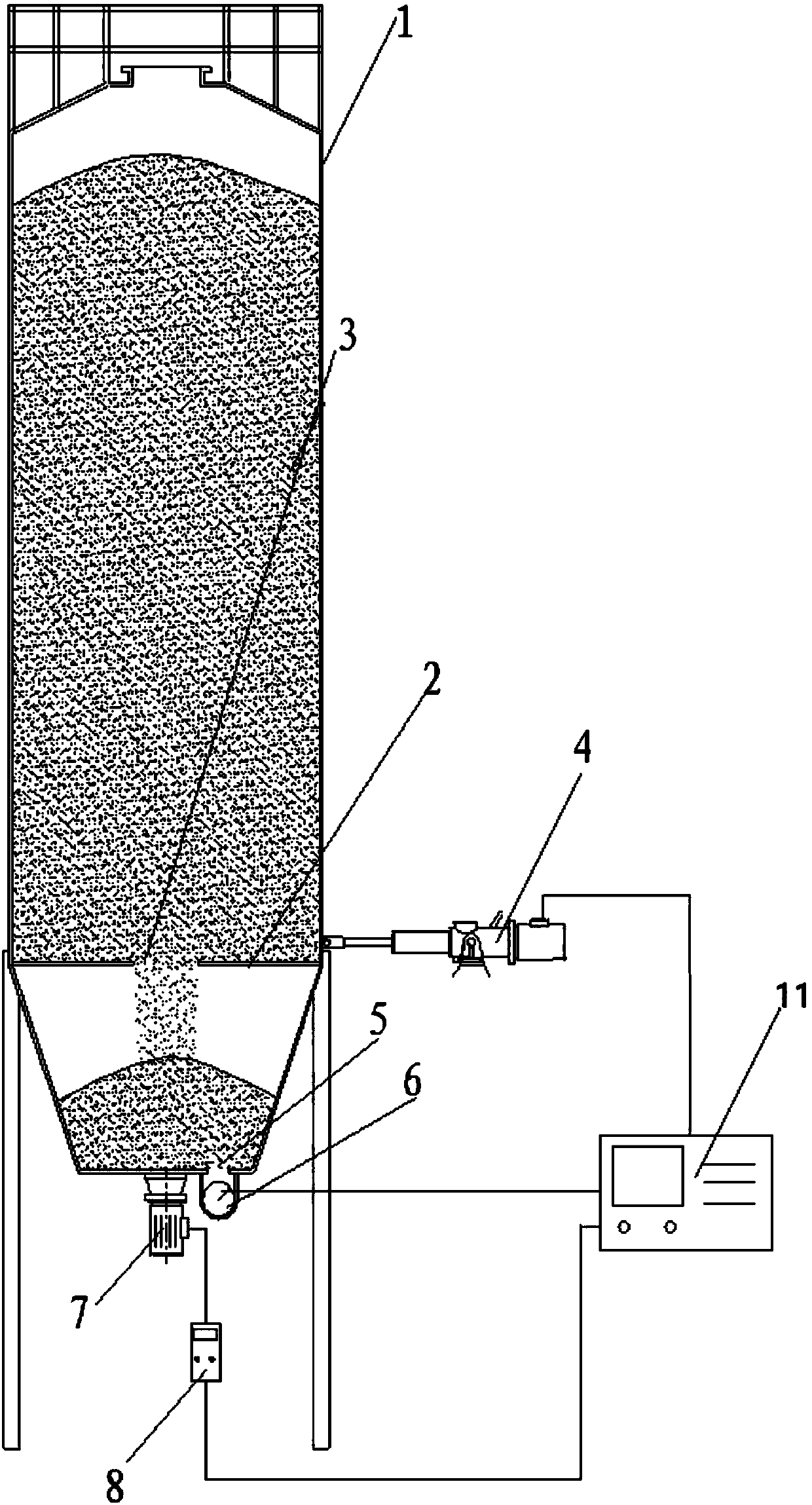
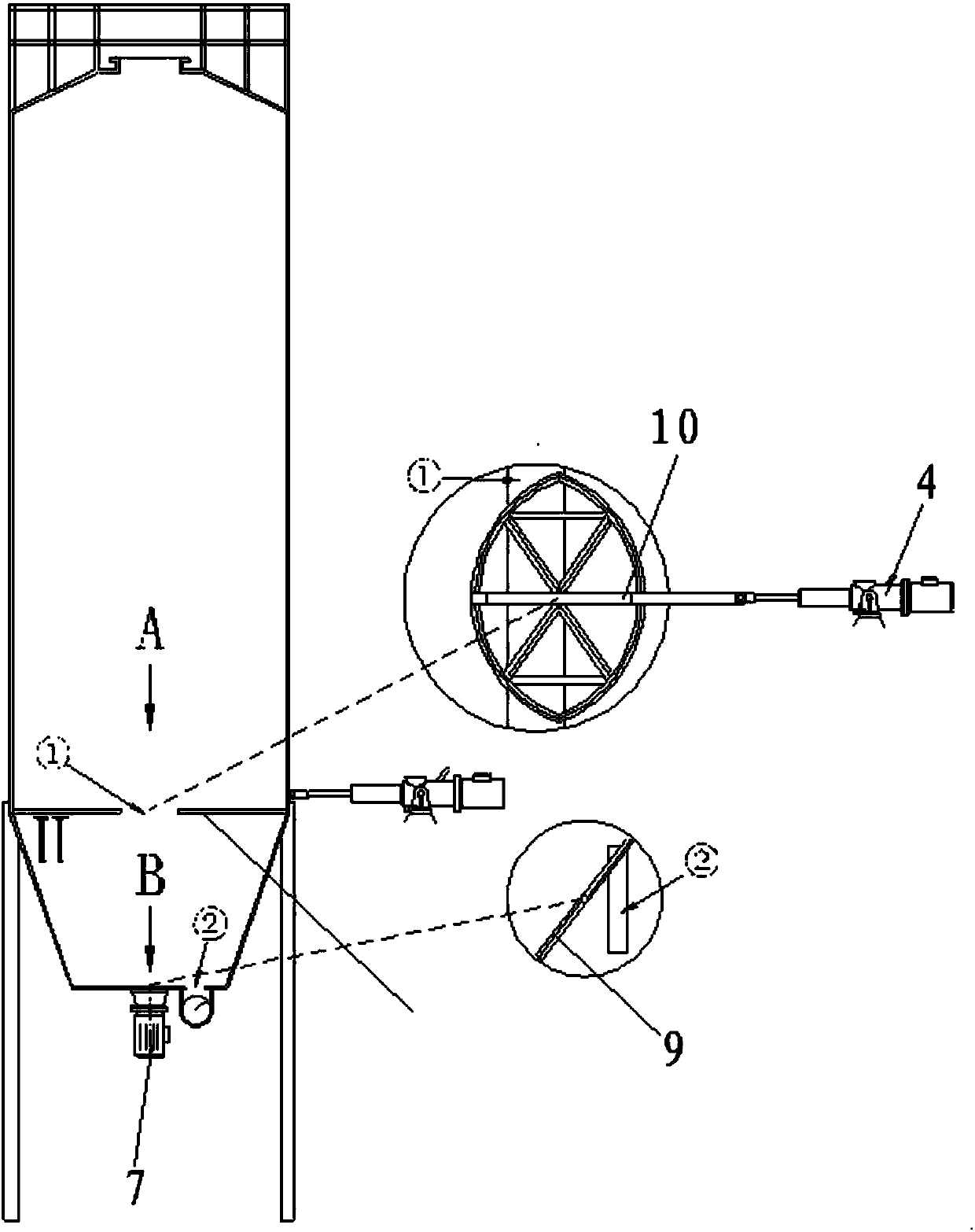
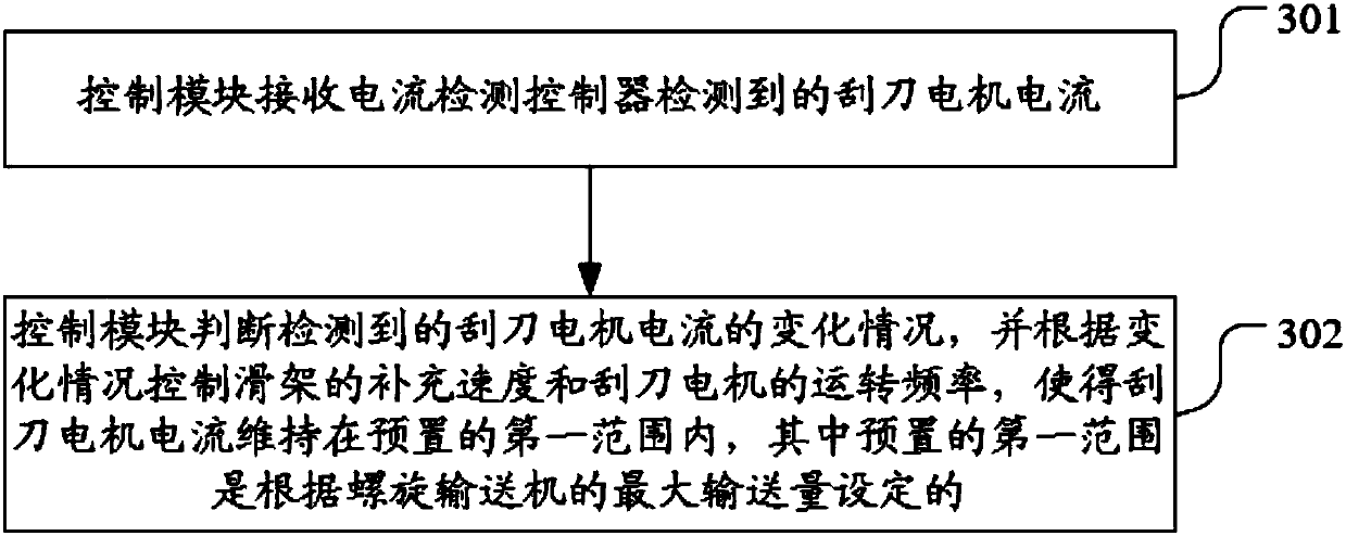
[0006] The embodiment of the present invention provides a material unloading device and a control method. The arch is broken and the material is replenished through the carriage arranged on the load-bearing partition, and the material is scraped to the first unloading gate through the scraper arranged at the bottom of the silo. , and finally transported out by the material conveyor. During the whole process of unloading, the control module controls the supplementary speed of the carriage and the operating frequency of the scraper motor according to the change of the scraper motor current detected by the current detection controller, so that the scraper motor The current is maintained within the preset first range, which not only ensures that the material replenishment amount of the carriage does not exceed the maximum conveying capacity of the material conveyor, but also ensures a relatively high conveying efficiency, which solves the problem that the existing large-scale silo passes through a single There are technical problems that the material conveyor cannot digest the amount of material when the material is broken when the mechanical unloading device is used for arch-breaking unloading, resulting in secondary blockage and uncontrollable uncontrollable unloading inside the silo

Method used


Image

  • Discharging device and control method
  • Discharging device and control method
  • Discharging device and control method

Examples


Embodiment Construction

[0042] The embodiment of the present invention provides a material unloading device and a control method. The arch is broken and the material is replenished through the carriage arranged on the load-bearing partition, and the material is scraped to the first unloading gate through the scraper arranged at the bottom of the silo. , and finally transported out by the material conveyor. During the whole process of unloading, the control module controls the supplementary speed of the carriage and the operating frequency of the scraper motor according to the change of the scraper motor current detected by the current detection controller, so that the scraper motor The current is maintained within the preset first range, so that the material replenishment of the carriage does not exceed the maximum conveying capacity of the material conveyor, which solves the problem of arch-breaking and unloading of the existing large-scale silo through a single mechanical unloading device The materi...


PUM


Abstract

The embodiment of the invention discloses a discharging device and a control method. Arch breaking and material supplementation are carried out through a carriage arranged on a bearing partition plate, materials are conveyed to a first discharging gate in a scraped mode through a scraper arranged at the bottom of a charge bin, and finally the materials are conveyed out through a material conveyor.In the whole discharging process, a control module controls the supplementation speed of the carriage and the running frequency of a scraper motor according to the change condition of a scraper motorcurrent detected by a current detection controller, so that the scraper motor current is maintained within a first preset range, the effect that the material supplementation quantity of the carriagedoes not exceeds the maximum conveying quantity of the material conveyor is ensured, high conveying efficiency is also ensured, and the technical problems that as an existing large charge bin adopts asimplex mechanical discharging device for arch breaking, the material conveyor cannot digest the discharging quantity in case of material slippage, then secondary blocking is caused and the discharging condition in the charge bin cannot be controlled are solved.

Description

technical field [0001] The invention relates to the field of blanking, in particular to a blanking device and a control method. Background technique [0002] Unloading refers to the process of unloading the material from the gate at the bottom of the silo and transporting it to the target location. Large tank silos are an important symbol of industrial scale. The large tanks in many factories have a capacity of about 100 cubic meters or even larger, which brings great challenges to the storage and transportation of materials. Due to the huge capacity, material storage is usually calculated on the order of tens of tons to hundreds of tons, so the difficulty of material storage and blanking increases geometrically with the scale of this capacity, especially for blanking There have always been a series of thorny problems in the link. Moreover, due to the poor fluidity of some materials, an auxiliary device (such as a rotary scraper) must be installed at the bottom of the sil...

Claims


Application Information

Patent Timeline
Patent Type & Authority Applications(China)
IPC IPC(8): B65G65/40B65D90/00B65D90/54
Inventor 曾秀仪陈沛波
Owner 深圳市泽源能源股份有限公司
Learn More