Joint connecting working method of a laminated-slab concrete composite precast component

A technology of prefabricated components and concrete, which is applied in the direction of building components, building structures, walls, etc., can solve the problems of difficult binding and difficult to guarantee the connection quality, and achieve the effect of simple binding, simple connection method and guaranteed connection quality

Pending Publication Date: 2018-01-19
湖北宇辉中工建筑产业化有限公司
View PDF6 Cites 4 Cited by
  • Summary
  • Abstract
  • Description
  • Claims
  • Application Information

AI Technical Summary

Problems solved by technology

The advancement of laminated slab concrete shear wall technology is reflected in the connection of steel bars. Most of the existing steel bar connections are anchored in cast-in-place concrete. The steel bars are connected in the cavity of the laminated slab concrete shear wall and bound. Difficult, the connection quality is difficult to guarantee

Method used


Image

  • Joint connecting working method of a laminated-slab concrete composite precast component
  • Joint connecting working method of a laminated-slab concrete composite precast component
  • Joint connecting working method of a laminated-slab concrete composite precast component

Examples


Embodiment 1

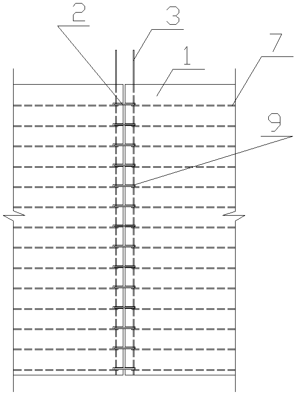
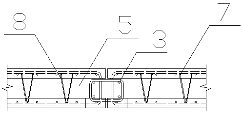
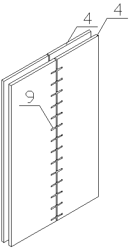
[0026] A superimposed slab type concrete composite prefabricated component connection, which consists of: a superimposed slab concrete prefabricated component 1, the superimposed slab concrete prefabricated component includes two concrete thin slabs 4, and a space is reserved between the two concrete thin slabs Cavity 5, the two concrete thin slabs are connected by truss steel bars 8, the laminated slab-type concrete prefabricated member has vertical steel bars 6 and horizontal steel bars 7, and the single-sided thin slabs of the two concrete thin plates have rectangular gaps 9. A connecting stirrup 2 is placed inside the rectangular gap, and a connecting longitudinal rib 3 is penetrated inside the connecting stirrup.

Embodiment 2

[0028] According to the superimposed slab concrete composite prefabricated component connection described in embodiment 1, the connecting stirrup is ring-shaped, and the ring shape adopts butt welding, 135° hook and 90° hook form, and the connection longitudinal The bars are straight bars, the horizontal bars are closed loops, and the connecting longitudinal bars are located at the corners of the gaps between the connecting stirrups and the horizontal bars.

Embodiment 3

[0030] According to the composite slab-type concrete composite precast member connection described in embodiment 1, the rectangular notches are at the same distance and the same number as the connecting stirrups, and the width of the rectangular notches is 10 larger than the diameter of the connecting stirrups. -30mm, the length of the rectangular notch is 10-30mm larger than the projection length of the concrete precast member at the theoretical connection position of the connecting stirrup, and the thickness of the rectangular notch is the same as the thickness of the single-sided thin slab of the two concrete thin slabs.


PUM


Abstract

The invention relates to a joint connecting working method of a laminated-slab concrete composite precast component. The problems that existing reinforcing bar connection adopts the mode that steel bars are anchored in cast-in-place concrete, the steels bars are connected in a cavity of a concrete shear wall, binding is difficult, and the connecting quality is difficult to guarantee are solved. The laminated-slab concrete composite precast component comprises a laminated-slab concrete precast component body (1). The laminated-slab concrete precast component body comprises two concrete thin plates (4). A cavity (5) is reserved between the concrete thin plates. The concrete thin plates are connected by a truss steel bar (8). The laminated-slab concrete precast component body is provided witha vertical reinforced bar (6) and a horizontal reinforced bar (7). A rectangular notch (9) is formed in the thin plate on the single side of the two concrete thin places. A connecting stirrup (2) isplaced in the rectangular notch, and a connecting longitudinal rib (3) is arranged in the connecting stirrup in a penetrating mode. The invention relates to a joint connecting working method of a laminated-slab concrete composite precast component.

Description

Technical field: [0001] The invention relates to a joint connection method of a laminated slab concrete composite prefabricated component. Background technique: [0002] Compared with the traditional cast-in-place structure, the prefabricated building has obvious technical advantages, saving labor, saving templates, saving machinery, improving survival quality, reducing emissions, reducing pollution, saving construction time and saving costs. But for different prefabricated construction methods, the economic and social benefits produced are different. The advancement of the laminated slab concrete shear wall technology is reflected in the connection of steel bars. Most of the existing steel connections are anchored in cast-in-situ concrete. The steel bars are connected in the cavity of the laminated slab concrete shear wall and tied Difficult, the connection quality is difficult to guarantee. Summary of the invention: [0003] The purpose of the present invention is to provide a...

Claims


Application Information

Patent Timeline
Patent Type & Authority Applications(China)
IPC IPC(8): E04B2/68
Inventor 刘文清闫红缨祝玉君马川峰
Owner 湖北宇辉中工建筑产业化有限公司
Why Eureka
Try Eureka