Spring safety valve debugging device

A safety valve and valve stem technology, applied in valve device, valve operation/release device, measuring device, etc., can solve the problems of neglecting friction force, poor adjustment accuracy of safety valve setting pressure, large tension, etc., and achieve accurate debugging. Effect

Pending Publication Date: 2018-01-19
HARBIN HBC VALVE
View PDF1 Cites 7 Cited by
  • Summary
  • Abstract
  • Description
  • Claims
  • Application Information

AI Technical Summary

Problems solved by technology

[0002] The existing spring safety valve on-line calibration device is generally simple in structure, only by listening to the sound to judge whether the valve is open, the accuracy of the setting pressure adjustment of the safety valve is poor, it has a lot to do with the experience and proficiency of the operator, and the operation process is complicated
[0003] Invention patent (patent number: CN 101368883 B) safety valve on-line calibration method introduces the device to calculate the pulling force of the safety valve by detecting the medium pressure of the input piston cylinder, ignoring the friction force of the piston, and the detected pulling force is too large; the device displacement sensor and The displacement of the valve stem of the safety valve is not directly detected, and whether the valve is opened or not is judged by detecting the displacement of the piston rod. Although the valve rod and the piston rod are rigidly connected, the piston rod will produce a slight displacement relative to the valve rod before the valve rod moves. Therefore, May misjudge valve opening

Method used


Image

  • Spring safety valve debugging device

Examples


Embodiment Construction

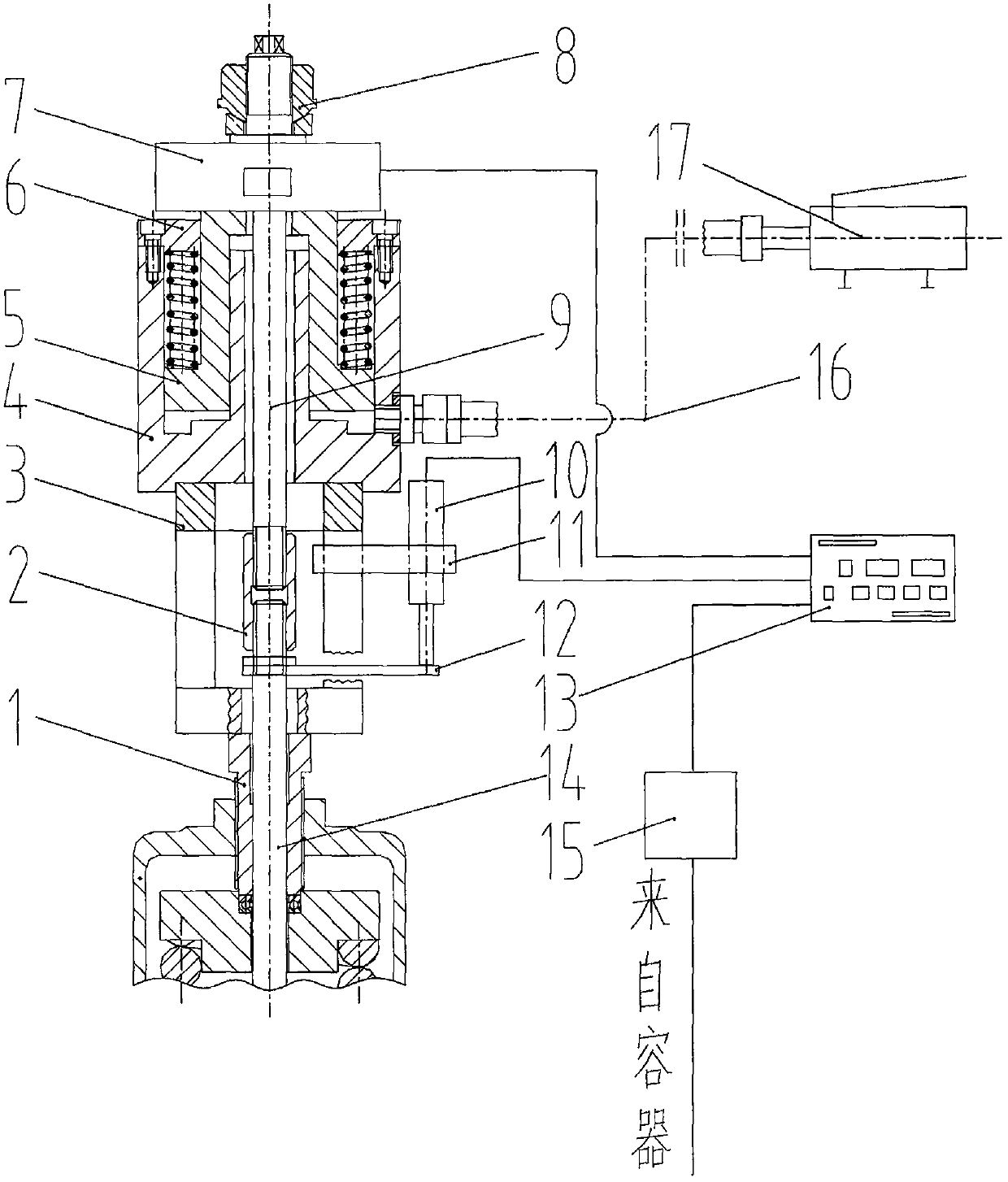
[0010] exist figure 1 In the shown embodiment, the bracket is placed on the adjustment screw of the safety valve, the hydraulic cylinder is placed on the bracket, the load cell is placed on the piston, the valve stem of the safety valve passes through the hydraulic cylinder and is rigidly connected to the pull rod through the connecting nut, and is tightened ten thousand times. Compress the load cell against the nut. When the safety valve is opened, the load cell can accurately measure the pulling force on the valve stem.

[0011] The displacement sensor is fixed on the bracket, and the stroke baffle is rigidly connected with the valve stem of the safety valve. Adjust the position of the displacement sensor so that the sensor is in contact with the stroke baffle to ensure accurate measurement of the actual displacement of the safety valve stem. Whether the safety valve is opened or not is judged by the displacement of the valve stem.

[0012] The pressure transmitter is conn...


PUM


Abstract

The invention relates to a spring safety valve debugging device which can perform online debugging and checking on a spring safety valve. The spring safety valve debugging device comprises a data processor, a force measuring sensor, a displacement transducer, a pressure transducer, a hydraulic cylinder, a bracket, a piston, a universal nut, a pull rod, a high-pressure oil pump and the like, wherein the hydraulic cylinder and the bracket are mounted on a regulating screw of the safety valve; a force measuring transducer is placed on the hydraulic cylinder; the pull rod passes through the hydraulic cylinder and is rigidly connected with a valve rod of the safety valve; and the displacement transducer is fixedly arranged on the bracket. During checking, high-pressure medium is injected into the hydraulic cylinder through the high-pressure oil pump, the piston drives a valve rod to move upwards, a measuring element transmits a displacement signal of valve opening, valve rod pull force andcontainer pressure data into a data processor, and set pressure and spring regulating amount of the safety valve are precisely calculated; and in a checking process, displacement of the valve rod is detected through the displacement sensor to judge whether the valve is opened or not. The spring safety valve debugging device has the advantages that set pressure of the spring safety valve can be precisely measured on line under pressure, and debugging and checking of the safety valve can be precisely and reliably performed according to the measured results.

Description

technical field [0001] The invention relates to a spring safety valve debugging device, which is mainly used for on-line debugging and verification of the setting pressure of spring direct-acting safety valves of various specifications, so as to ensure the accuracy of the setting pressure during on-line verification of the safety valve. Background technique [0002] The existing on-line calibration devices for spring safety valves are generally simple in structure, and only rely on listening to the sound to judge whether the valve is open. [0003] Invention patent (patent number: CN 101368883 B) safety valve on-line calibration method introduces the device to calculate the pulling force of the safety valve by detecting the medium pressure of the input piston cylinder, ignoring the friction force of the piston, and the detected pulling force is too large; the device displacement sensor and The displacement of the valve stem of the safety valve is not directly detected, and w...

Claims


Application Information

Patent Timeline
Patent Type & Authority Applications(China)
IPC IPC(8): F15B11/028F15B19/00F16K37/00F16K31/122G01M13/00
Inventor 万胜军
Owner HARBIN HBC VALVE
Why Eureka
Try Eureka