Safe type valve
A safety type, valve technology, applied in the direction of sliding valve, valve detail, valve device, etc., can solve the problems of enhanced control safety, unfavorable fluid delivery safety and stability, complicated control operation, etc.
- Summary
- Abstract
- Description
- Claims
- Application Information
AI Technical Summary
Problems solved by technology
Method used
Image
Examples
Embodiment 1
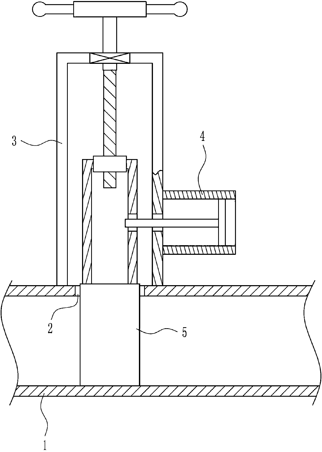
[0032] A safety valve such as Figure 1-7 As shown, it includes a through pipe 1, a working groove 3, a bolt insertion device 4 and a blocking device 5. The top wall of the through pipe 1 is provided with a through hole 2, and the top of the through pipe 1 is provided with a working groove 3, and the working groove 3 is located in the through hole 2. The top of the working tank 3 is provided with a blocking device 5, and the bottom right of the working tank 3 is provided with a plugging device 4, and the plugging device 4 cooperates with the blocking device 5.
Embodiment 2
[0034] A safety valve such as Figure 1-7 As shown, it includes a through pipe 1, a working groove 3, a bolt insertion device 4 and a blocking device 5. The top wall of the through pipe 1 is provided with a through hole 2, and the top of the through pipe 1 is provided with a working groove 3, and the working groove 3 is located in the through hole 2. The top of the working tank 3 is provided with a blocking device 5, and the bottom right of the working tank 3 is provided with a plugging device 4, and the plugging device 4 cooperates with the blocking device 5.
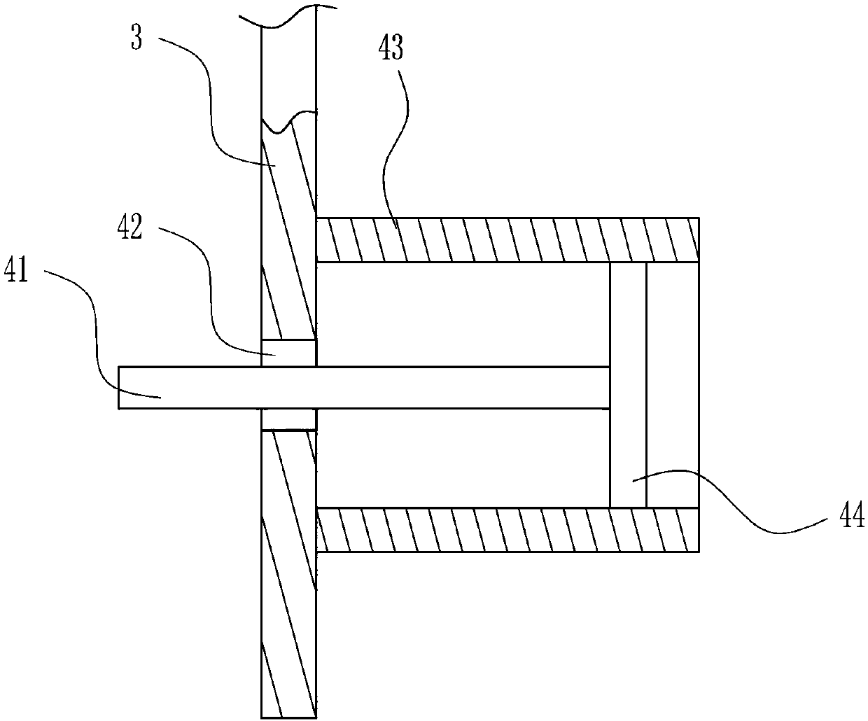
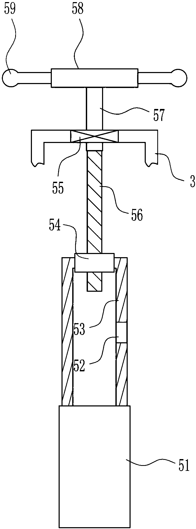
[0035] The bolt insertion device 4 includes an insertion rod 41, a fixed frame 43 and a rotating rod 44, the right wall of the working groove 3 is provided with a moving hole 42, the right side of the working groove 3 is provided with a fixed frame 43, and the fixed frame 43 is provided with a rotating rod 44, An insertion rod 41 is provided on the left side of the rotating rod 44 , and the insertion rod 41 passes thro...
Embodiment 3
[0037] A safety valve such as Figure 1-7 As shown, it includes a through pipe 1, a working groove 3, a bolt insertion device 4 and a blocking device 5. The top wall of the through pipe 1 is provided with a through hole 2, and the top of the through pipe 1 is provided with a working groove 3, and the working groove 3 is located in the through hole 2. The top of the working tank 3 is provided with a blocking device 5, and the bottom right of the working tank 3 is provided with a plugging device 4, and the plugging device 4 cooperates with the blocking device 5.
[0038] The bolt insertion device 4 includes an insertion rod 41, a fixed frame 43 and a rotating rod 44, the right wall of the working groove 3 is provided with a moving hole 42, the right side of the working groove 3 is provided with a fixed frame 43, and the fixed frame 43 is provided with a rotating rod 44, An insertion rod 41 is provided on the left side of the rotating rod 44 , and the insertion rod 41 passes thro...
PUM
 Abstract
Description
Claims
Application Information
 - R&D
- Intellectual Property
- Life Sciences
- Materials
- Tech Scout
- Unparalleled Data Quality
- Higher Quality Content
- 60% Fewer Hallucinations
Browse by: Latest US Patents, China's latest patents, Technical Efficacy Thesaurus, Application Domain, Technology Topic, Popular Technical Reports.
© 2025 PatSnap. All rights reserved.Legal|Privacy policy|Modern Slavery Act Transparency Statement|Sitemap|About US| Contact US: help@patsnap.com


