
Discontinuous field matching method for general beam-wave interaction model of traveling wave tube
A technology of injection-wave interaction and matching method, which is applied in the field of discontinuous field matching of the general injection-wave interaction model of traveling wave tubes, can solve the problem of long calculation time, difficulty in establishing theoretical model of injection-wave interaction parameters, and inability to simulate travel Wave tube and other issues to achieve the effect of increasing practicability
- Summary
- Abstract
- Description
- Claims
- Application Information
AI Technical Summary
Problems solved by technology
Method used
Image

Examples
Embodiment Construction
[0022] The technical solutions of the present invention will be further described below in conjunction with the accompanying drawings and specific embodiments.
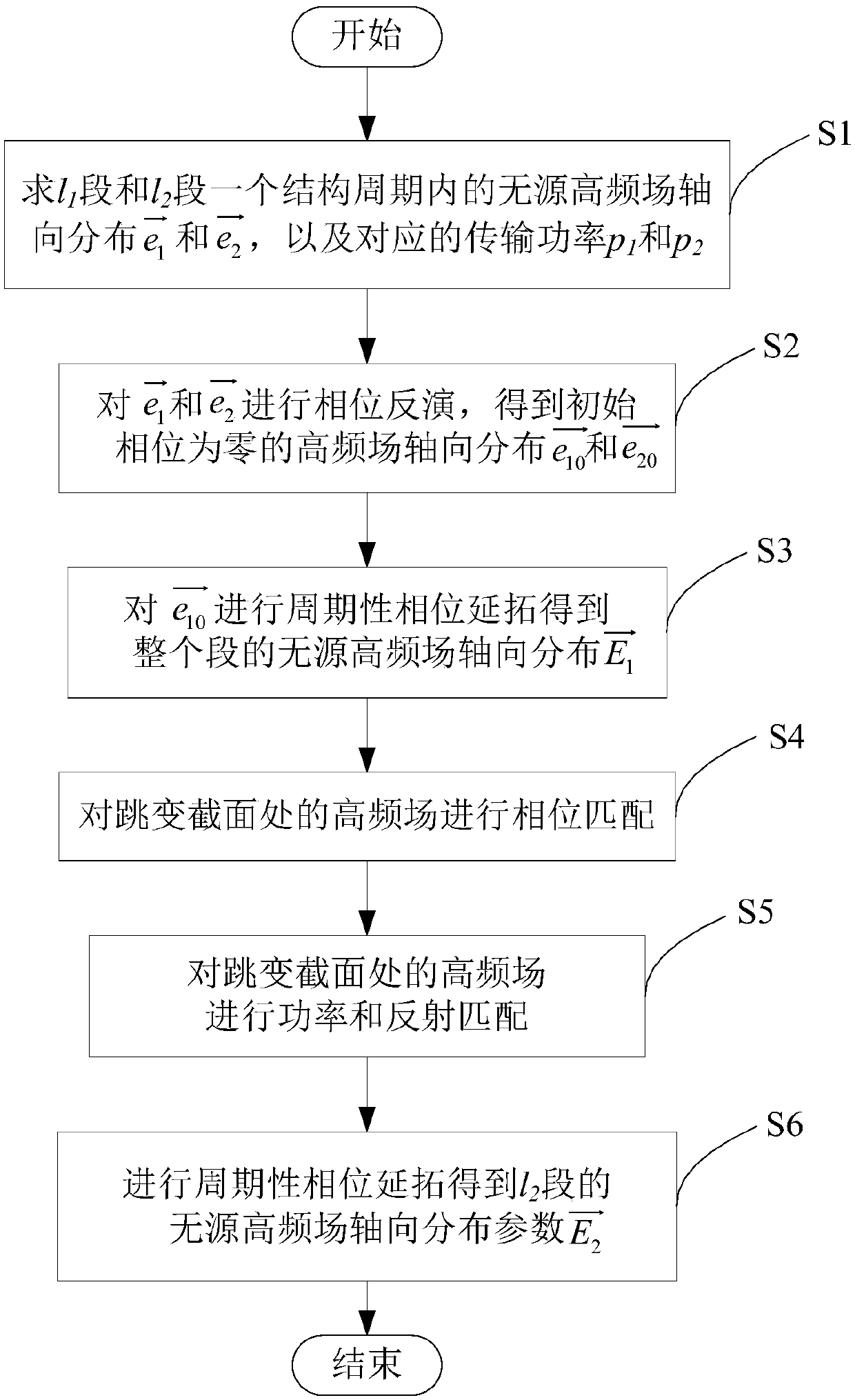
[0023] Such as figure 1 As shown, a discontinuous field matching method for the general injector-wave interaction model of a traveling wave tube includes the following steps:
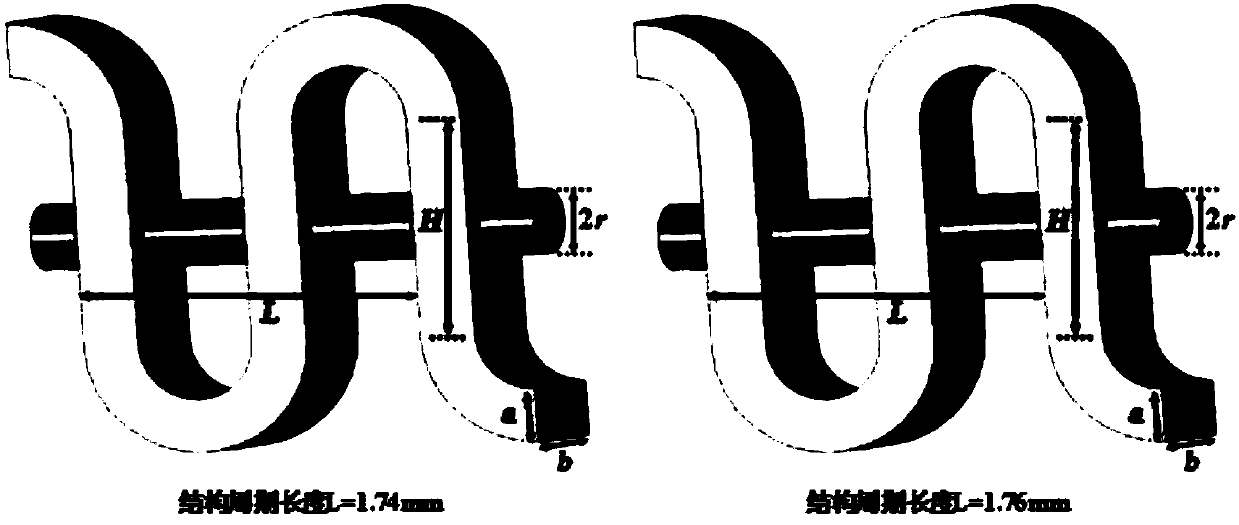
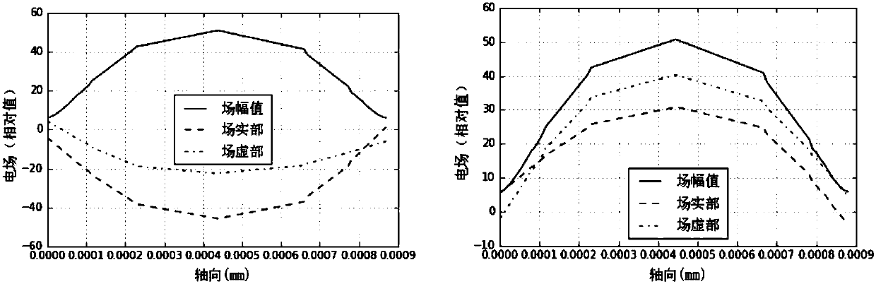
[0024] S1. Denote the folded waveguide before the jump of the high-frequency structure of the traveling wave tube injection wave interaction as l 1 segment, and its structural period length is denoted as L 1 ; The folded waveguide after the jump is denoted as l 2 segment, and its structural period length is denoted as L 2 ; Utilize the three-dimensional high-frequency simulation software HFCS for l 1 segment and l 2 L 1 and L 2 Carry out scanning calculation for the parameter, this embodiment sets the number of radial grids to be 20, the number of angular grids to be 20, and the number of axial grids to be 50; get l 1 segment and l 2 T...
PUM
 Abstract
Description
Claims
Application Information