
Small-aperture, high-gain and broadband dielectric rod antenna

A dielectric rod and high-gain technology, applied in the field of dielectric rod antennas, can solve the problems of low antenna bandwidth, pull-up, and inability to fully utilize the broadband advantages of dielectric rods, and achieve structural optimization, impedance bandwidth, and high-gain directional radiation Effect

Inactive Publication Date: 2018-01-19
HARBIN INST OF TECH
View PDF2 Cites 6 Cited by
  • Summary
  • Abstract
  • Description
  • Claims
  • Application Information

AI Technical Summary

Problems solved by technology

However, the improvement of gain is often accompanied by the increase of the antenna aperture size, thus increasing the minimum test distance of the antenna, which is very unfavorable for the measurement work using a small darkroom
[0004] Therefore, in order to solve the contradiction between aperture size and gain, dielectric rod-loaded lenses have received extensive attention. These dielectric rod-loaded antennas are often directly loaded on the waveguide interface, resulting in low antenna bandwidth and unable to fully utilize the broadband advantages of dielectric rods.

Method used


Image

  • Small-aperture, high-gain and broadband dielectric rod antenna
  • Small-aperture, high-gain and broadband dielectric rod antenna
  • Small-aperture, high-gain and broadband dielectric rod antenna

Examples


specific Embodiment

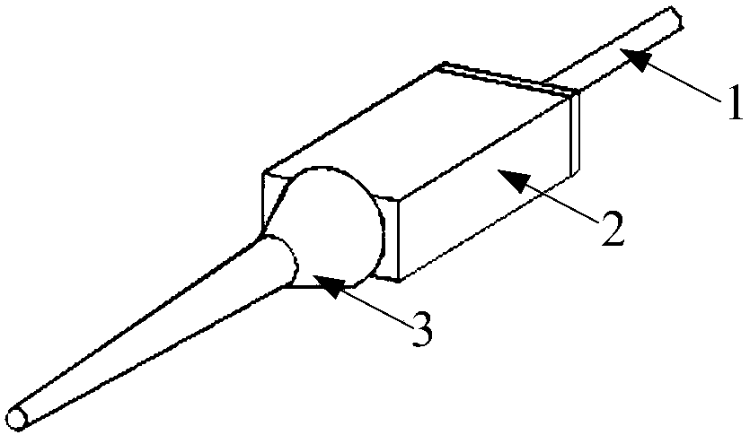
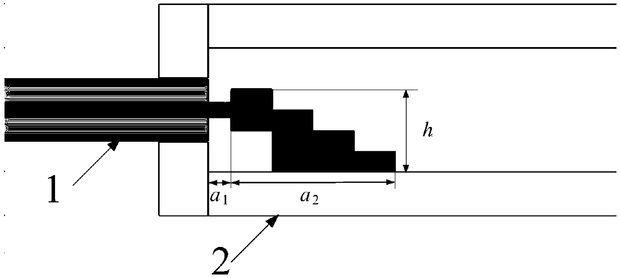
[0039] Specific embodiments: this embodiment provides the specific dimensions of the connecting end including the feed structure 1 and the dielectric rod lens 3:

[0040] The step block structure is realized by four steps, the height of the four steps is equal, the total height h of the four steps is 2.87mm, the width of each step block is 2.6mm, and the total length of the step block is a 2 is 5mm, the distance a between the high end of the step block and the end face of the transmission waveguide 2 1 is 0.7mm.

[0041] The length of the wedge groove I 1 is 15.5mm, the length of the rectangular block I 2 9.2mm;

[0042] The transition section is a circular platform with a height of 10mm, the diameter of the large end is 4.68mm, and the diameter of the small end is 10.7mm;

[0043] The transmission section is a circular platform with a height of 44mm, the diameter of the large end is 10.7mm, and the diameter of the small end is 2mm;

[0044] The radiation section is a hem...


PUM


Abstract

The invention provides a small-aperture, high-gain and broadband dielectric rod antenna, which belongs to the field of radio technology. The antenna includes a feeding structure, a transmission waveguide, and a dielectric rod lens. The connection end of the feeding structure is connected with one end of the transmission waveguide, and one end of the dielectric rod lens is inserted into the other end of the transmission waveguide. The connection end of the feeding structure is of a stepped block structure. The dielectric rod lens includes a matching section, a transition section, a transmissionsection, and a radiation section. The matching section, the transition section, the transmission section and the radiation section are connected in sequence as a whole. The matching section is inserted into the other end of the transmission waveguide. By introducing the stepped block structure, the impedance bandwidth is improved. By optimizing the dielectric rod structure, broadband high-gain directional radiation is realized.

Description

technical field [0001] The invention relates to a dielectric rod antenna, in particular to a directional radiation antenna, which belongs to the technical field of radio. Background technique [0002] In order to reduce the minimum test distance of the antenna, it is necessary to reduce the aperture of the antenna, and the reduction of the aperture will reduce the gain of the antenna. [0003] In order to increase the gain of the aperture antenna, loading the lens is a very effective means. However, the increase in gain is often accompanied by the increase in the antenna aperture size, thus increasing the minimum test distance of the antenna, which is very unfavorable for the measurement work using a small darkroom. [0004] Therefore, in order to solve the contradiction between aperture size and gain, dielectric rod-loaded lenses have received extensive attention. These dielectric rod-loaded antennas are often directly loaded on the waveguide interface, resulting in a low ...

Claims


Application Information

Patent Timeline
Patent Type & Authority Applications(China)
IPC IPC(8): H01Q1/36H01Q1/50
Inventor 林澍毛宇毕延迪刘冠君
Owner HARBIN INST OF TECH
Learn More