Directional gain antenna

A directional gain antenna, antenna technology, applied in the direction of antenna, slot antenna, antenna coupling, etc., can solve the problem that the antenna gain effect is not very good, achieve the effect of directional radiation characteristics, reduce the possibility, and suppress the side lobe

Active Publication Date: 2019-05-10
SHENZHEN TCL NEW-TECH CO LTD
View PDF29 Cites 0 Cited by
  • Summary
  • Abstract
  • Description
  • Claims
  • Application Information

AI Technical Summary

Problems solved by technology

[0005] The main purpose of the present invention is to provide a directional gain antenna, which aims to solve the problem that the antenna gain effect of directional emission in the prior art is not very good

Method used


Image

  • Directional gain antenna
  • Directional gain antenna
  • Directional gain antenna

Examples


Embodiment Construction

[0027] It should be understood that the specific embodiments described here are only used to explain the present invention, not to limit the present invention.

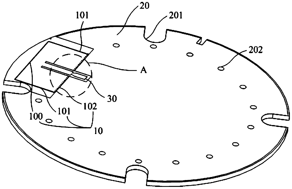
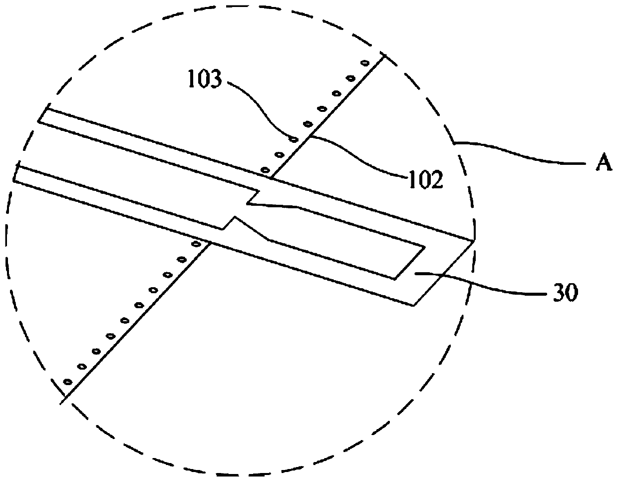
[0028] Such as Figure 1-2 as shown, figure 1 It is a structural schematic diagram of the directional gain antenna of the present invention; figure 2 It is the enlarged view of A in the present invention.

[0029] refer to figure 1 , figure 1 It is a structural schematic diagram of the directional gain antenna of the present invention.

[0030] The present invention provides a directional gain antenna. The directional gain antenna includes an antenna body 10 and a metal main board 20. The antenna body 10 is arranged on the metal main board 20, and the distance between the antenna body 10 and the edge of the metal main board 20 is smaller than the antenna body 10 and the metal main board 20. the distance between the centers of the metal main boards 20;

[0031] The antenna body 10 is connected with a microstrip ...


PUM


Abstract

The invention discloses a directional gain antenna. The directional gain antenna comprises an antenna body and a metal main board, wherein the antenna body is arranged on the metal main board, the distance between the antenna body and the metal main body is smaller than the distance between the antenna body and a center of the metal main board, the antenna body is connected with a microstrip line,an antenna surface is formed, a radiation gap is formed in the antenna body, the distance between the radiation gap and an edge of the metal main board is smaller than the distance between the radiation gap and the center of the metal main board, sidelobe in the antenna surface is prevented through the microstrip line by an electric wave when the antenna body emits the electric wave, and radiation is performed through the radiation gap. By the directional gain antenna, the gain improvement of forward scattering of a metal surface of the metal main board is achieved, directional radiation of the antenna surface is achieved, the possibility of same-frequency interference can be reduced, and radiation in other directions can be effectively prevented.

Description

technical field [0001] The invention relates to the technical field of antennas, in particular to directional gain antennas. Background technique [0002] Antenna is an important and necessary component for transmitting and receiving electromagnetic wave energy in a wireless communication system. [0003] Based on intelligent voice interaction, the commonly used Bluetooth antenna as a terminal application seldom considers the directionality of the antenna radiation. When the communication method is relatively certain in the project application, it is hoped that the energy can be projected to the application area as much as possible to improve the communication effect. This proposes directed launch. [0004] However, the antenna gain effect of the existing directional transmission is not very good. Contents of the invention [0005] The main purpose of the present invention is to provide a directional gain antenna, aiming at solving the problem in the prior art that the a...

Claims


Application Information

Patent Timeline
Patent Type & Authority Applications(China)
IPC IPC(8): H01Q23/00H01Q13/10H01Q1/22H01Q1/36H01Q1/52
Inventor 尹柳中郭康清谢仁礼王子同杨福军
Owner SHENZHEN TCL NEW-TECH CO LTD
Why Eureka
Try Eureka