
Low-profile ultra-wideband directional radiation antenna

A directional radiation, low-profile technology, applied in the direction of antenna, radiating element structure, antenna grounding switch structure connection, etc., can solve the problems of limiting the application of ultra-wideband directional antenna and the large vertical size of the antenna.

Active Publication Date: 2018-02-16
HARBIN INST OF TECH
View PDF3 Cites 0 Cited by
  • Summary
  • Abstract
  • Description
  • Claims
  • Application Information

AI Technical Summary

Problems solved by technology

[0003] At present, a series of new ultra-wideband antennas have been proposed, including various shaped monopoles and symmetrical dipoles to achieve omnidirectional radiation, while the ultra-wideband directional antenna is LPDA (logarithmic periodic antenna array composed of symmetrical dipoles, log- periodicdipole antenna), TEM (Transverse Electro Magnetic) horn, ridged horn and Vivaldi antenna, etc., the longitudinal dimensions of these antennas are large, which limits the application of ultra-wideband directional antennas

Method used


Image

  • Low-profile ultra-wideband directional radiation antenna
  • Low-profile ultra-wideband directional radiation antenna
  • Low-profile ultra-wideband directional radiation antenna

Examples


specific Embodiment

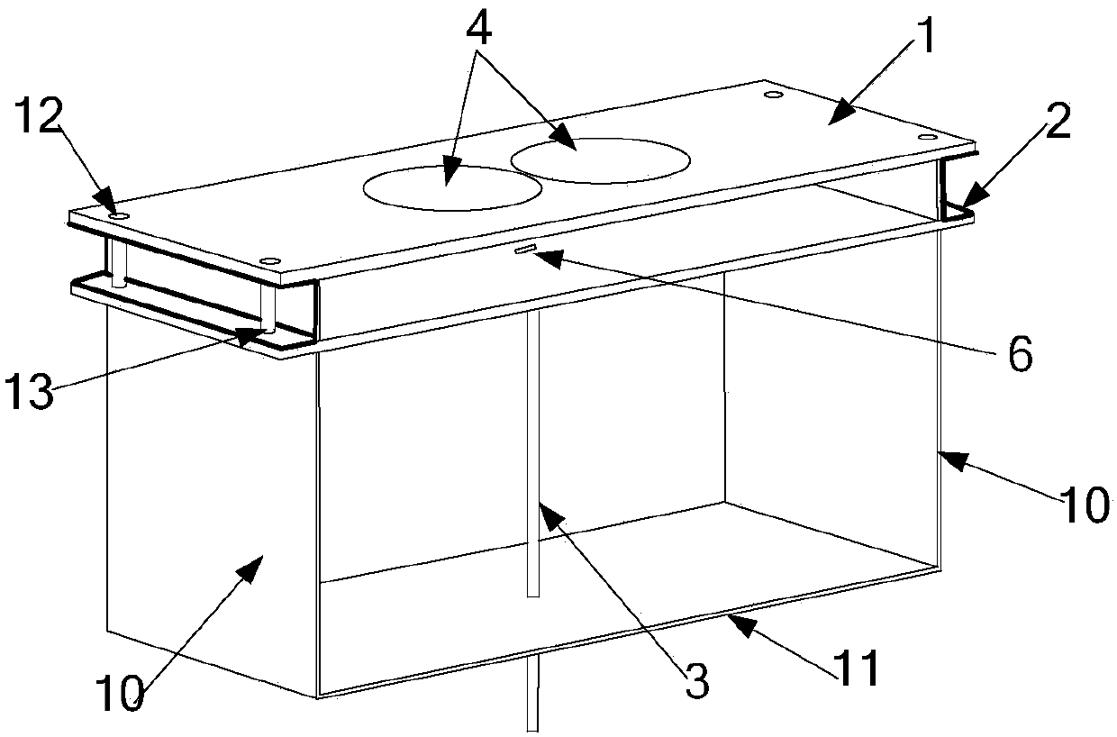
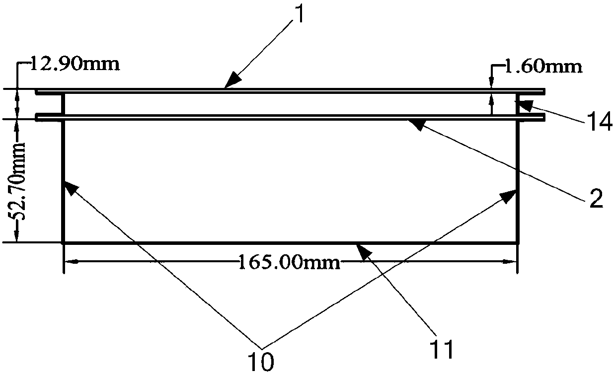
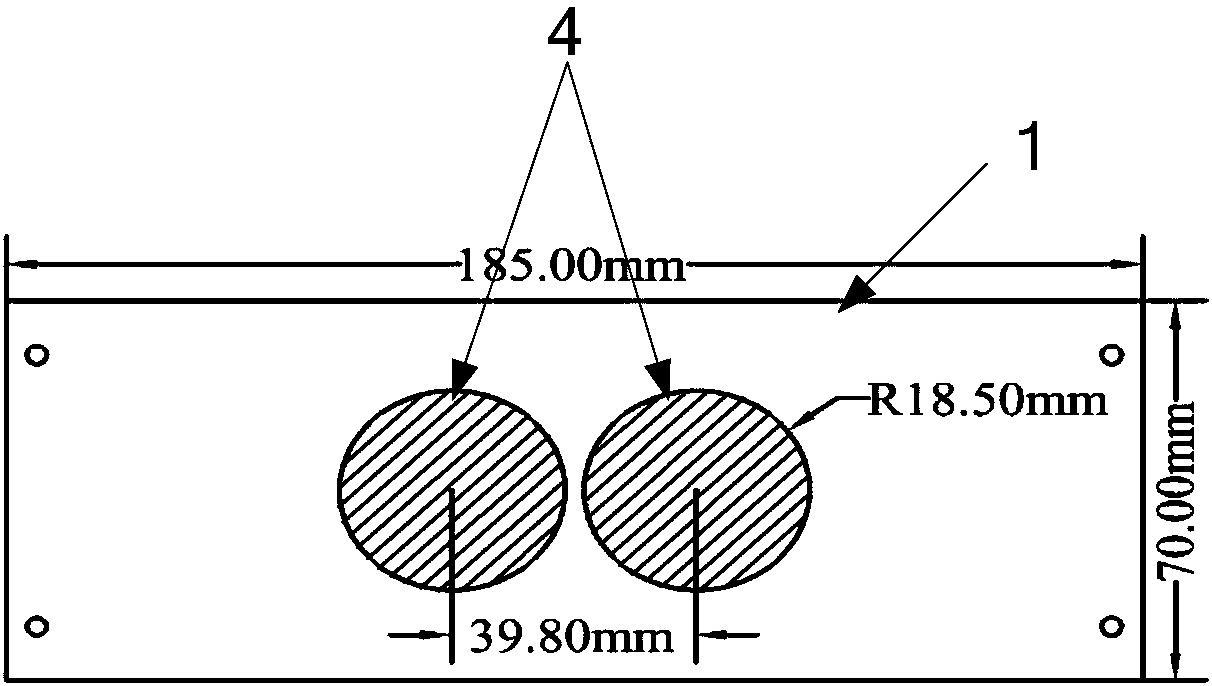
[0058] Specific embodiments: This embodiment provides a low-profile ultra-wideband directional radiation antenna. The specific dimensions of the antenna are as follows: Figure 1 to Figure 5 Shown:

[0059] The distance between the top surface of the upper dielectric board 1 and the bottom surface of the lower board 2 is 12.9mm;

[0060] The distance between the bottom surface of the lower dielectric plate 2 and the bottom surface of the reflective bottom plate 11 is 52.7 mm, and the distance between the two reflective side walls 10 is 165 mm;

[0061] Both ends of the upper dielectric plate 1 and the lower dielectric plate 2 are 10 mm longer than the joints with the reflective walls 10 on both sides;

[0062] Both the upper dielectric board 1 and the lower dielectric board 2 have a width of 70mm.

[0063] The radius of the disk 4 of the symmetrical vibrator director is 18.5 mm, and the distance between the centers of the two disks 4 is 39.8 mm.

[0064] The radius of the p...


PUM


Abstract

The invention provides a low-profile ultra-wideband directional radiation antenna with relatively low longitudinal dimensions, and belongs to the field of radio technology. The low-profile ultra-wideband directional radiation antenna comprises an upper dielectric plate, a lower dielectric plate, a coaxial line feed structure, an irregularly-shaped symmetrical oscillator structure, symmetrical oscillator directors and a metal baffle board with a bending structure, wherein the metal baffle board with the bending structure passes through the lower dielectric plate and the upper dielectric plate from bottom to top in sequence, and an interval is preserved between the lower dielectric plate and the upper dielectric plate; the symmetrical oscillator directors are printed on the top surface of the upper dielectric plate, the symmetrical oscillator directors comprise two discs with same semi-diameters, and the distance of the circle centers of the two discs is greater than the diameters of thediscs; the irregularly-shaped symmetrical oscillator structure is printed on the bottom surface of the lower dielectric plate, the printed form irregularly-shaped oscillator structure comprises two symmetrical active oscillator arms, each active oscillator arm consists of two printed wafers with same semi-diameter respectively, and the distance of the circle centers of the two wafers is smaller than the diameters of the wafers; and the top surface of the lower dielectric plate is connected with the coaxial line feed structure.

Description

technical field [0001] The invention relates to an ultra-wideband antenna, in particular to a low-profile directional radiation antenna, which belongs to the field of radio technology. Background technique [0002] Ultra-wideband antennas have a wide operating frequency band and can cover multiple standard communication frequency bands. Therefore, they have become an effective means of realizing antenna miniaturization and have received extensive research and attention. [0003] At present, a series of new ultra-wideband antennas have been proposed, including various shaped monopoles and symmetrical dipoles to achieve omnidirectional radiation, while the ultra-wideband directional antenna is LPDA (logarithmic periodic antenna array composed of symmetrical dipoles, log- periodicdipole antenna), TEM (Transverse Electro Magnetic) horn, ridged horn, and Vivaldi antenna, etc., the longitudinal dimensions of these antennas are large, which limits the application of ultra-wideband ...

Claims


Application Information

Patent Timeline
Patent Type & Authority Applications(China)
IPC IPC(8): H01Q1/38H01Q1/50H01Q5/10H01Q5/20H01Q5/307H01Q19/02H01Q19/10
CPCH01Q1/38H01Q1/50H01Q5/10H01Q5/20H01Q5/307H01Q19/02H01Q19/106
Inventor 林澍毛宇毕延迪刘冠君
Owner HARBIN INST OF TECH
Learn More