Multi-beam integrated waveguide antenna use for on-board anti-collision radar
An integrated waveguide and anti-collision radar technology, which is applied in the direction of antenna, antenna grounding switch structure connection, radiation element structure, etc., can solve the difficulty of anti-collision radar target algorithm, complex anti-collision radar system hardware, and high price of anti-collision radar and other problems, to achieve the effect of easy low side lobe control, light weight and simple structure
- Summary
- Abstract
- Description
- Claims
- Application Information
AI Technical Summary
Problems solved by technology
Method used
Image
Examples
Embodiment 1
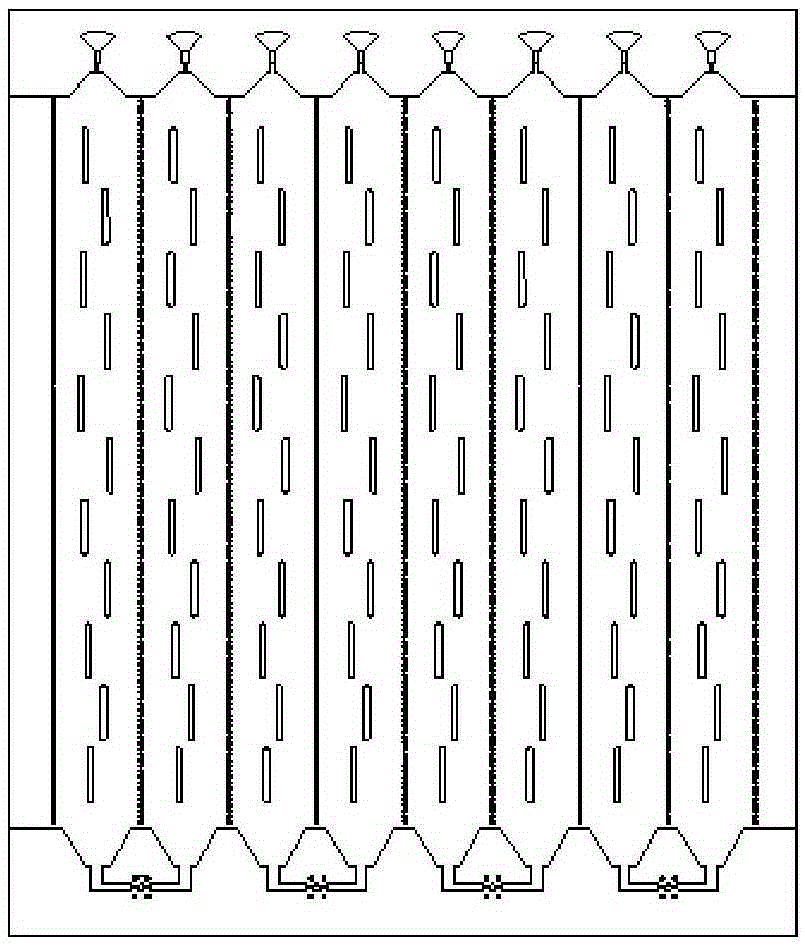
[0036] A multi-beam integrated waveguide antenna for vehicle-mounted anti-collision radar, the substrate integrated waveguide antenna array of the first layer, (2n-2) layers of striplines, and the bottom microwave circuit are integrated; the microwave circuit is mainly composed of X One-point (2n-1) unequal power dividers, (2n-1) one-point X unequal power dividers, where n+1 is the number of beams formed, n≥2, X is the number of array antennas number of units.
[0037] Further, the X feed points of the substrate integrated waveguide antenna array on the first layer are connected to the main path of a (2n-1) unequal power divider of the microwave circuit on the bottom layer through through holes;
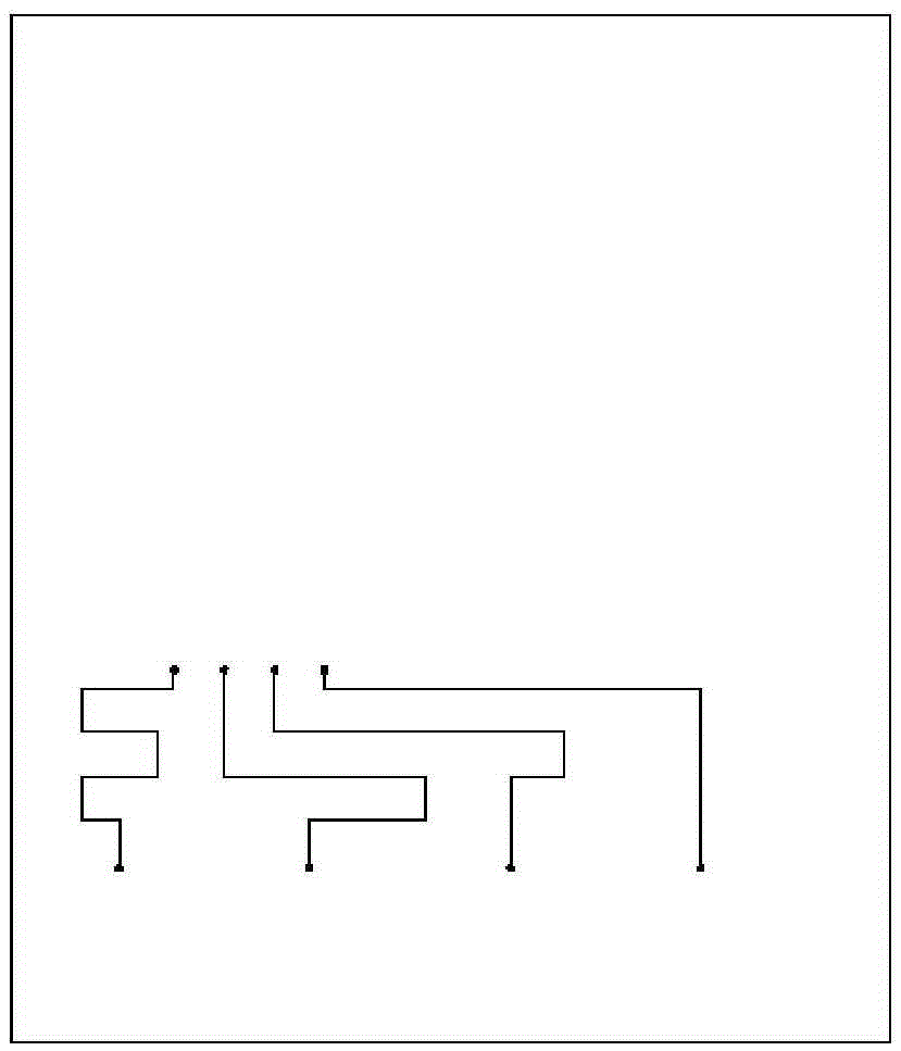
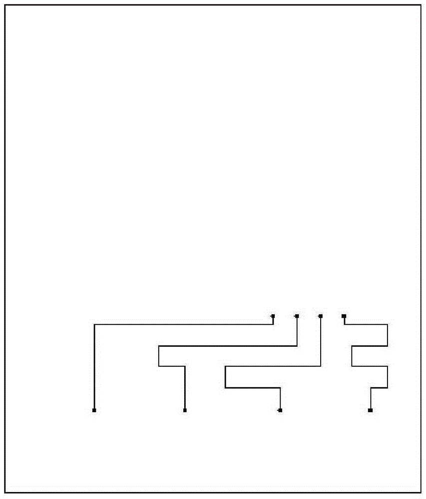
[0038] The first branch of each (2n-1) unequal power divider is connected to the stripline of the second layer through the via hole, and the stripline of the second layer is connected to the first one of the bottom layer through the via hole. Divide X branches of X unequal power div...
Embodiment 2
[0046] A three-beam integrated waveguide antenna for vehicle-mounted anti-collision radar, which consists of a substrate integrated waveguide antenna array 1 on the first layer, a stripline 2 on the second layer, a stripline 3 on the third layer, and an integrated waveguide antenna array on the fourth layer. The microwave circuit 4 is integrated, and the microwave circuit 4 is composed of four one-to-three unequal power dividers 7 , three one-to-four unequal power dividers 6 , four equal-phase microstrip lines and a microwave switch network 5 .
[0047] Further, the four feeding points of the substrate integrated waveguide antenna array 1 on the first layer are connected to the main path of the one-to-three unequal power divider 7 of the microwave circuit 4 on the fourth layer through through holes;
[0048] The first branch of each one-to-three unequal power divider 7 is connected to the stripline 2 of the second layer through a via hole, and is connected to the first one-to-f...
Embodiment 3
[0055] It has the same technical solution as that of Embodiment 2, and more specifically, the substrate-integrated waveguide antenna array is loaded with load matching resistors. Adjacent antennas are combined by a power splitter first, and then power distribution and phase weighting are performed. The microwave switch network is a single-pole three-throw switch network. The two-layer stripline structure is symmetrical, and the phase shift is an arithmetic sequence, one is positive and the other is negative. The phases of the microstrip lines between the one-to-three unequal power divider and the one-to-four unequal power divider are equal, and the resistance of the load matching resistor is 100Ω.
[0056] The multi-beam integrated waveguide antenna of this embodiment can realize spatial filtering at the front end of the radio frequency, can effectively suppress clutter signals, and only needs to switch the microwave switch network, and can realize the judgment of targets in ...
PUM
 Abstract
Description
Claims
Application Information
 - R&D
- Intellectual Property
- Life Sciences
- Materials
- Tech Scout
- Unparalleled Data Quality
- Higher Quality Content
- 60% Fewer Hallucinations
Browse by: Latest US Patents, China's latest patents, Technical Efficacy Thesaurus, Application Domain, Technology Topic, Popular Technical Reports.
© 2025 PatSnap. All rights reserved.Legal|Privacy policy|Modern Slavery Act Transparency Statement|Sitemap|About US| Contact US: help@patsnap.com


