Broadband directional microstrip patch antenna

A microstrip patch antenna and microstrip feeder technology, applied in the application field of communication technology, can solve the problems of increasing the complexity of installation, increasing the complexity of processing, unfavorable antenna installation and fixing, etc., and achieves increased isolation and high processing accuracy. , the effect of improving cross-polarization performance

Inactive Publication Date: 2012-10-17
SOUTHEAST UNIV
View PDF4 Cites 17 Cited by
  • Summary
  • Abstract
  • Description
  • Claims
  • Application Information

AI Technical Summary

Problems solved by technology

[0005] Most of the existing microstrip patch antenna arrays adopt a multi-layer structure, and the gap between the feed network and the slotted ground plane is filled with a dielectric plate, and the gap between the radiating patch and the gap is often filled with foam or air to widen the bandwidth. Increases the complexity of processing, which is not conducive to the installation and fixation of the antenna
[0006] In occasions such as base station antennas, the antennas are often placed at high places. In order to enhance the signal strength of the coverage area, the mechanical downtilt method is now mostly used, which increases the complexity of installation.

Method used


Image

  • Broadband directional microstrip patch antenna
  • Broadband directional microstrip patch antenna
  • Broadband directional microstrip patch antenna

Examples


Embodiment 1

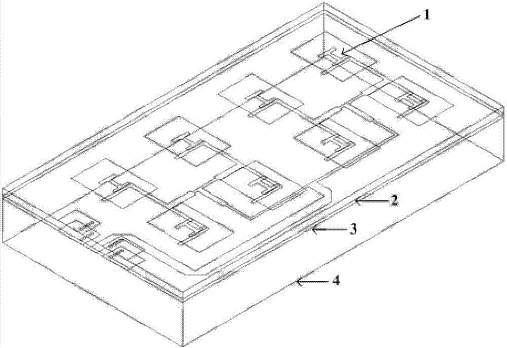
[0032] Embodiment 1: Vertically Polarized Broadband Microstrip Patch Antenna with 15° Tilt Angle

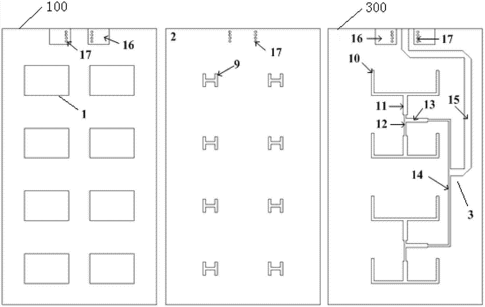
[0033] Antenna structure such as figure 1 As shown, the structure of each layer is as follows figure 2 shown. The total size of the antenna with the metal reflector 4 is 105mm×59mm×15.5mm (L×W×H). The thickness of the dielectric layer between the radiation patch array 1 and the metal ground plane 2 is 2 mm, the thickness of the dielectric layer between the metal ground plane 2 and the microstrip feeder network 3 is 1 mm, and the dielectric constant of the dielectric substrate as the dielectric layer is uniform Taconic (Taconic) for 2.55. The horizontal spacing of patch units is 25mm, and the vertical spacing is 24mm. An H-shaped slot 9 of 5.5mm×5mm is opened on the metal grounding surface 2, and the slot width is 1mm. The longitudinal dimension of the open-circuit microstrip line 10 is 9.5mm, the transverse dimension is equal to the transverse spacing of patch units of 25mm...

Embodiment 2

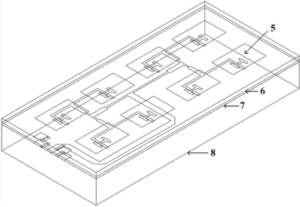
[0034] Embodiment 2: Horizontally polarized broadband microstrip patch antenna with 15° inclination angle

[0035] Antenna structure such as image 3 As shown, the structure of each layer is as follows Figure 4 shown. The total size of the antenna with the metal reflector 8 is 111mm×51mm×15.5mm (L×W×H). The thickness of the dielectric layer between the radiation patch array 5 and the metal ground plane 6 is 2 mm, the thickness of the dielectric layer between the metal ground plane 6 and the microstrip feeder network 7 is 1 mm, and the dielectric substrates used as the dielectric layer have a dielectric constant Taconic (Taconic) for 2.55. The horizontal spacing of patch units is 22mm, and the vertical spacing is 25mm. An H-shaped slot 18 of 5.5 mm×4.5 mm is opened on the metal ground plane 6 with a slot width of 1 mm. The transverse dimension of the open circuit microstrip line 19 is 9mm, the longitudinal dimension is equal to the vertical spacing of the chip units being...


PUM


Abstract

The invention discloses a broadband directional microstrip patch antenna which is sequentially provided with a first medium layer, a microstrip feeder network arranged on the first medium layer, a second medium layer, a slit grounding surface arranged on the second medium layer, a third medium layer and a radiation patch array arranged on the third medium layer from bottom to top. The broadband directional microstrip patch antenna is simple to process and easy to assemble.

Description

technical field [0001] The invention belongs to the application field of communication technology, and in particular relates to a broadband directional microstrip patch antenna. Background technique [0002] In recent years, wireless communication technology has developed rapidly and has been widely used. Antennas are key components of wireless communication systems. Modern communication systems require antennas that are low cost, easy to fabricate, and easy to integrate with other microwave radio frequency planar circuits. At present, low-frequency communication has tended to be saturated, so high-frequency, directional radiation, easy-to-fabricate, and easy-to-integrate antennas have become one of the new research hotspots. [0003] The microstrip patch can realize directional radiation with vertical polarization or horizontal polarization. The radiation gain of a single microstrip patch is limited, and a series-fed array or a parallel-fed array can be used to increase t...

Claims


Application Information

Patent Timeline
Patent Type & Authority Applications(China)
IPC IPC(8): H01Q1/38H01Q13/08H01Q21/24
Inventor 周健义杨汶汶
Owner SOUTHEAST UNIV
Why Eureka
Try Eureka