A method for obtaining pressure-sensitive feedback for luminous flux changes on a single optical component

A technology of luminous flux and optical components, applied in the input/output, electrical components, computer parts and other directions of user/computer interaction, which can solve the problem of inability to obtain pressing speed and pressing position, high cost of optical receivers, and discontinuous signals, etc. problems, to achieve timely and sensitive feedback, low production costs, and not easy to wear

Active Publication Date: 2021-01-26
GUANGDONG RUIXUN ELECTRONIC TECH CO LTD
View PDF18 Cites 0 Cited by
  • Summary
  • Abstract
  • Description
  • Claims
  • Application Information

AI Technical Summary

Problems solved by technology

[0002] The existing potential switch can only obtain two kinds of signals by blocking or not blocking the light receiver by the baffle, and cannot obtain the signal during the pressing process; at the same time, due to the small area of ​​the CCD, the height of the CCD is much smaller than the movement distance of the baffle , the baffle shifts a short distance during the pressing process to block the light receiver, making it impossible to obtain accurate pressing speed and pressing position
So someone came up with the idea of ​​setting up multiple optical receivers to obtain the signal during the pressing process, but the interruption of such signals is discontinuous, and the cost of adding optical receivers is high, and it is difficult to arrange and install multiple optical receivers in sequence

Method used


Image

  • A method for obtaining pressure-sensitive feedback for luminous flux changes on a single optical component
  • A method for obtaining pressure-sensitive feedback for luminous flux changes on a single optical component
  • A method for obtaining pressure-sensitive feedback for luminous flux changes on a single optical component

Examples


Embodiment Construction

[0033] The present invention will be described in further detail below in conjunction with the accompanying drawings and specific embodiments.

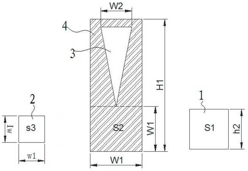
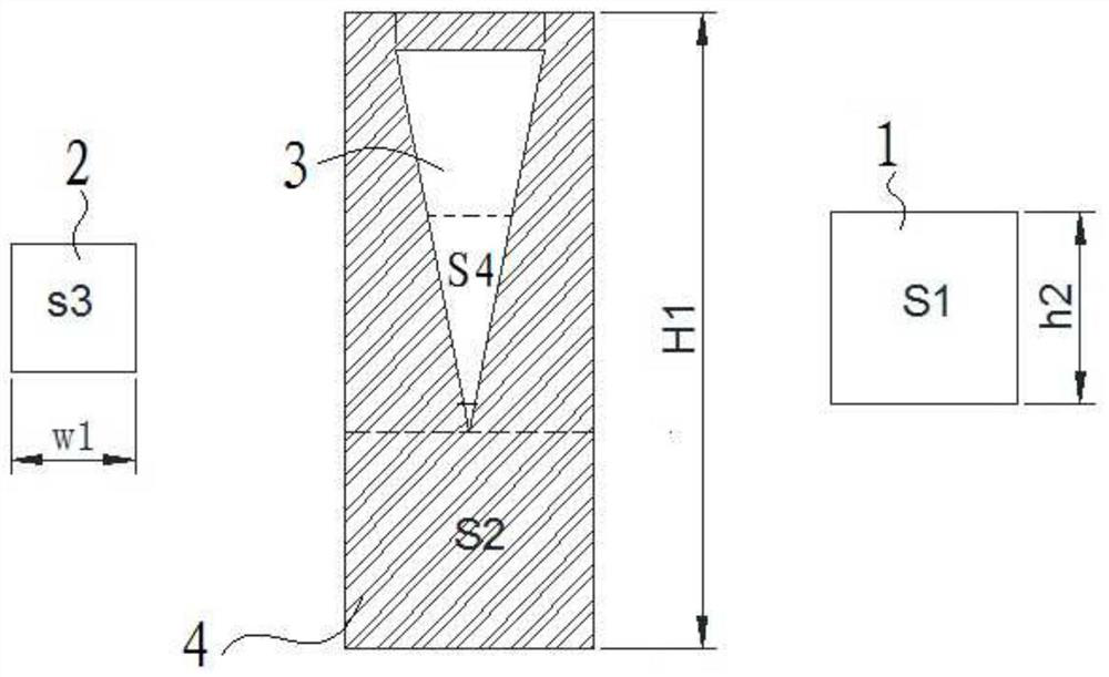
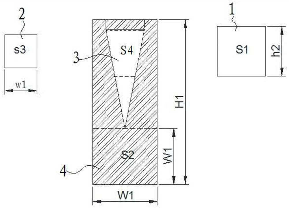
[0034] Such as Figure 1-7 As shown, the method for achieving pressure-sensitive feedback on a single light component to realize luminous flux changes includes a single light-receiving element 2 and a light-emitting element 1 that provides a light source for the light-receiving element. A switch assembly, the switch assembly includes a button part and a dimming board, the dimming board includes a base area 4 and a dimming area 3, the light transmission coefficient of the dimming area 4 is different from that of the base area 3, the dimming board Displacement occurs as the button is pressed;

[0035] Among them, the active distance of the dimmer is H1, and the height of the illuminated area of ​​the light-emitting element is h2, where H1 is much larger than h2;

[0036] The maximum light-blocking width W1 of the dimming board, the wi...


PUM


Abstract

The invention discloses a method for obtaining pressure-sensitive feedback on a single optical component to realize luminous flux change. When the button is pressed, the dimming area of ​​the dimming board gradually decreases, and the dimming area S4 of the dimming area changes, corresponding to the dimming area S4 of the dimming area. The light emitted by the light plate through the light-emitting element changes, and the luminous flux Φ at this time also changes correspondingly. Due to the movement of the dimming area, the luminous flux Φ obtained by the light-receiving element changes; and then the real-time pressing position is obtained by calculating the changed luminous flux Φ H, through the real-time position H, the pressed gravity and the pressed position can be calculated, and then any level of pressure-sensitive feedback can be obtained. This application only needs a single optical component to obtain the pressed gravity and pressed position, realize any level of pressure-sensitive feedback, and then realize the corresponding pressure-sensitive operation through simulation; the structure adopted by the method of this application is convenient to install and assemble, and the production cost Low, when in use, the feedback obtained by pressing is timely and sensitive, the service life is long, and it is not easy to wear.

Description

technical field [0001] The invention relates to the field of potential switches, in particular to a method for achieving pressure-sensitive feedback for realizing luminous flux changes on a single optical component. Background technique [0002] The existing potential switch can only obtain two kinds of signals by blocking or not blocking the light receiver by the baffle, and cannot obtain the signal during the pressing process; at the same time, due to the small area of ​​the CCD, the height of the CCD is much smaller than the movement distance of the baffle , The light receiver is blocked when the baffle is displaced for a short distance during the pressing process, and accurate pressing speed and pressing position cannot be obtained. So someone came up with the idea of ​​setting up multiple optical receivers to obtain the signal during the pressing process, but such signals are intermittent and discontinuous, and the cost of adding optical receivers is high, and it is dif...

Claims


Application Information

Patent Timeline
Patent Type & Authority Patents(China)
IPC IPC(8): H03K17/96G06F3/01
CPCG06F3/01H03K17/96
Inventor 李建平
Owner GUANGDONG RUIXUN ELECTRONIC TECH CO LTD
Why Eureka
Try Eureka