
Rectangular external spline machining method suitable for numerical control turning center

A processing method and external spline technology, applied in the field of CNC turning parts processing, can solve the problems of high manufacturing cost, long processing cycle, difficult to popularize and apply, etc., and achieve simple and efficient processing methods, shortened processing period, and simple processing steps. Effect

Active Publication Date: 2018-01-23
CHENGDU AIRCRAFT INDUSTRY GROUP
View PDF9 Cites 3 Cited by
  • Summary
  • Abstract
  • Description
  • Claims
  • Application Information

AI Technical Summary

Problems solved by technology

The milling method is to use a special forming milling cutter on the milling machine to directly mill out the inter-tooth contour, and use the dividing head to divide the teeth into tooth-by-tooth milling. The disadvantage is that the productivity and accuracy are low.
The hobbing method is processed by the spline hob on the spline shaft hobbing machine according to the generating method. Its disadvantage is that special machine tools and hobbing cutters are required, and the manufacturing cost is high and the cycle is long.
The grinding method is to use a forming grinding wheel to grind the side surface and bottom diameter of the spline tooth on the spline shaft, which is suitable for processing hardened spline shafts or those with higher precision requirements. The disadvantage is that special machine tools and grinding wheels are required, and the processing cycle long, expensive
However, these methods have high requirements for equipment, and are difficult to be widely used in small and medium batch production.

Method used


Image

  • Rectangular external spline machining method suitable for numerical control turning center
  • Rectangular external spline machining method suitable for numerical control turning center
  • Rectangular external spline machining method suitable for numerical control turning center

Examples


Embodiment 1

[0028] Embodiment 1: A method for machining rectangular external splines suitable for CNC turning centers, characterized in that it comprises the following steps:

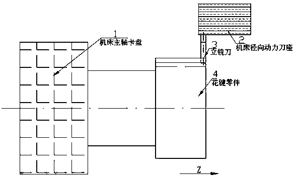
[0029] a: Parts and tools are installed as figure 1 As shown, tool selection, according to the material of the workpiece to be processed, select the material of the milling cutter, the diameter of the roughing tool should be smaller than the width of the keyway, and the diameter D of the finishing tool should be less than or equal to 1 / 2 the width of the keyway W (ie D≤1 / 2W), The bottom angle r of the milling cutter is equal to the fill angle R of the keyway (that is, r=R);

[0030] b: Rough machining of the keyway of the external spline, leaving a margin of 0.1~0.2mm on each surface;

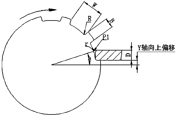
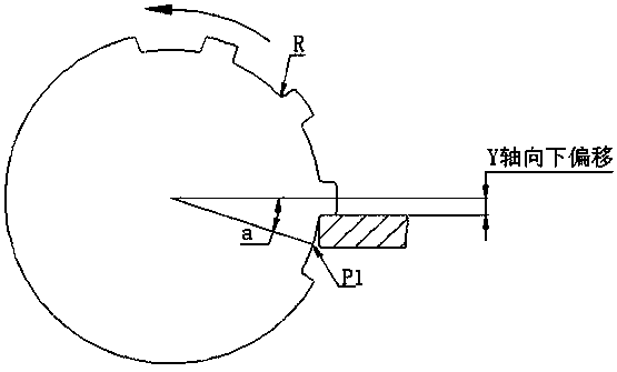
[0031] c: if figure 2 As shown, the fine milling of the upper side teeth of the spline is performed by using the precise positioning function of the C-axis of the turning center to rotate and position the spline teeth horizontall...

Embodiment 2

[0039] A method for machining rectangular external splines suitable for numerically controlled turning centers, characterized in that it comprises the following steps:

[0040] a: According to the material of the processed part, select the material of the milling cutter. The diameter of the roughing tool should be smaller than the width of the keyway, the diameter D of the finishing tool should be less than or equal to 1 / 2 the width of the keyway W, and the bottom angle r of the milling cutter is equal to the fillet angle R of the keyway;

[0041] b: Rough machining of the keyway of the external spline, leaving allowances on each surface;

[0042] c: Finish milling the upper side teeth of the spline obtained in step b, use the precise positioning function of the C-axis of the turning center to rotate and position the spline teeth horizontally, and then use the Y-axis function of the turning center to offset the tool upward by 1 / 2 tooth width B;

[0043] d: Quilt the upper ha...

Embodiment 3

[0048] A method for machining rectangular external splines suitable for numerically controlled turning centers, characterized in that it comprises the following steps:

[0049] a: According to the material of the processed part, select the material of the milling cutter. The diameter of the roughing tool should be smaller than the width of the keyway, the diameter D of the finishing tool should be less than or equal to 1 / 2 the width of the keyway W, and the bottom angle r of the milling cutter is equal to the fillet angle R of the keyway;

[0050] b: Rough machining of the keyway of the external spline, leaving allowances on each surface;

[0051] c: Finish milling the upper side teeth of the spline obtained in step b, use the precise positioning function of the C-axis of the turning center to rotate and position the spline teeth horizontally, and then use the Y-axis function of the turning center to offset the tool upward by 1 / 2 tooth width B;

[0052]d: Quilt the upper hal...


PUM


Abstract

The invention belongs to the field of numerical control turning part machining, and particularly relates to a rectangular external spline machining method suitable for a numerical control turning center. The rectangular external spline machining method is characterized by comprising the following steps that a, a milling cutter material is selected according to the material of a part to be machined; b, rough machining is carried out on an external spline groove, and allowances are reserved for all faces; c, finish milling is carried out on teeth on the upper side of the spline obtained in the step b; d, quilting cutting machining is carried out on the small-diameter upper half part of the spline obtained in the step c; e, teeth on the lower side of the spline obtained in the step d are machined; and f, the small-diameter lower half part of the spline is subjected to quilting cutting machining, and an end mill is arranged on a radial driven tool holder.

Description

technical field [0001] The invention belongs to the field of CNC turning parts processing, and in particular relates to a rectangular external spline processing method suitable for a CNC turning center. Background technique [0002] Rectangular splines are mostly used for shaft collar connections that transmit torque and often slip, requiring special processing equipment and forming tools. Traditional spline processing usually has three methods: milling, hobbing and grinding. The milling method is to use a special forming milling cutter to directly mill out the inter-tooth contour on a milling machine, and use a dividing head to divide the teeth into tooth-by-tooth milling. The disadvantage is that the productivity and accuracy are low. The gear hobbing method is to use the spline hob to process it on the spline shaft hobbing machine according to the generating method. Its disadvantage is that special machine tools and gear hobbing cutters are required, and the manufacturin...

Claims


Application Information

Patent Timeline
Patent Type & Authority Applications(China)
IPC IPC(8): B23C3/00B23P15/14
Inventor 王永洪陈思涛汪小东贺鹏飞陈中阳
Owner CHENGDU AIRCRAFT INDUSTRY GROUP
Learn More