Rapid clearing method for inner wall burrs of pipes

A technology for burrs and pipe fittings, which is applied in the field of rapid removal of burrs on the inner wall of pipe fittings, can solve the problems of reducing the service life of steel pipes, reducing strength, and reducing the stability of steel pipes, so as to reduce the probability of stress fracture, strengthen support stability, and improve transportation. The effect of efficiency

Inactive Publication Date: 2018-01-23
李明义
View PDF0 Cites 0 Cited by
  • Summary
  • Abstract
  • Description
  • Claims
  • Application Information

AI Technical Summary

Problems solved by technology

[0002] After the steel pipe is partially welded, the weld seam is directly exposed to the air. Due to the difference between the air temperature and the temperature of the weld seam itself, the weld seam will directly change from high temperature to low temperature. The strength of the steel pipe reduces the stability of the steel pipe. In severe cases, it will directly cause the weld seam of the steel pipe to be de-welded; and a certain amount of burrs will be generated on the inside and outside of the steel pipe near the weld seam during welding, so that the flow rate of the fluid in the steel pipe will decrease when the steel pipe is in use. Moreover, the protrusions at the weld seam are also easily corroded, which leads to a decrease in the overall strength of the weld seam and reduces the service life of the steel pipe; traditional internal burr removal equipment mainly focuses on the solder residue at the weld seam and the periphery of the weld seam and the raised However, the solder residue and protrusions scattered to other parts of the inner wall of the steel pipe during welding are not cleaned thoroughly

Method used


Image

  • Rapid clearing method for inner wall burrs of pipes
  • Rapid clearing method for inner wall burrs of pipes

Examples


Embodiment 1

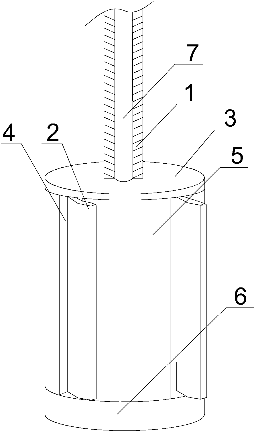
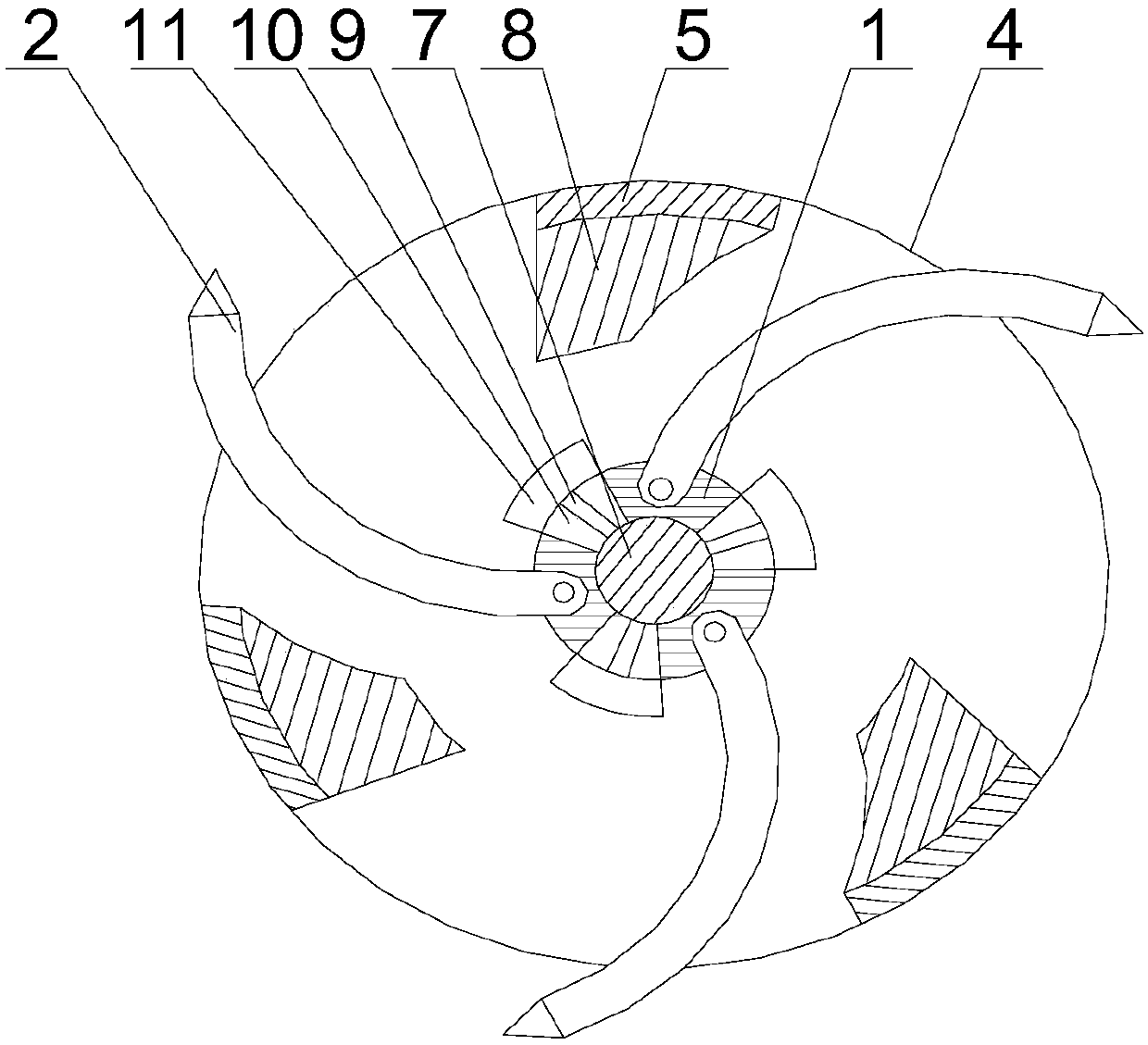
[0019] Such as figure 1 and figure 2 As shown, in this embodiment, according to the specific size of the inner diameter of the steel pipe, by rotating the screw, the relative movement between the screw and the central axis occurs, and the connecting rod moves in the fan-shaped hole while driving the stopper to move accordingly, realizing the stopper and cutting. The distance between the slices increases or decreases, forcing the position of multiple cutting slices to change, that is, the part of the cutting slices extending outward through the adjustment hole increases or decreases, so that the excessive movement of the blade tips of the multiple cutting slices The size of the annular area matches the inner diameter of the steel pipe, and then the external drive equipment drives the central shaft to rotate, and the cutting blade on the central shaft rotates to start cleaning the dirt on the inner wall of the steel pipe;

[0020] Wherein, the fixed plate 3 will be sealed with...


PUM


Abstract

The invention discloses a rapid clearing method for inner wall burrs of pipes. According to the specific size of the inner diameter of a steel pipe, relative motion between a screw rod and a central shaft is caused by rotating the screw rod; connecting rods drive stop blocks to move along with the connecting rods while the connecting rods move in fan-shaped holes, thus the distance between the stop blocks and cutting pieces is increased or reduced, the positions of the multiple cutting pieces are forced to change, namely the part, which extends outwards through a corresponding adjusting hole,of each cutting piece is increased or reduced, and the size of an annular area formed when the blade tips of the multiple cutting pieces move is matched with the inner diameter of the steel pipe; thecentral shaft is driven by an external driving device to rotate, and the cutting pieces positioned on the central shaft rotates and start removing the scale on the inner wall of the steel pipe; and the protruding height of scale on the inner wall of the steel tube is reduced after a cylinder rotates for several circles, the screw rod rotates again, so that the portion, extending outwards, of eachcutting piece is increased so as to enlarge the cleaning radius of the cutting pieces, secondary cleaning of the inner wall of the steel pipe is realized, and then the scale is cleaned thoroughly.

Description

technical field [0001] The invention relates to the field of cleaning dirt on the inner wall of pipe fittings, in particular to a method for quickly removing burrs on the inner wall of pipe fittings. Background technique [0002] After the steel pipe is partially welded, the weld seam is directly exposed to the air. Due to the difference between the air temperature and the temperature of the weld seam itself, the weld seam will directly change from high temperature to low temperature. The strength of the steel pipe reduces the stability of the steel pipe. In severe cases, it will directly cause the weld seam of the steel pipe to be de-welded; and a certain amount of burrs will be generated on the inside and outside of the steel pipe near the weld seam during welding, so that the flow rate of the fluid in the steel pipe will decrease when the steel pipe is in use. Moreover, the protrusions at the weld seam are also easily corroded, which leads to a decrease in the overall str...

Claims


Application Information

Patent Timeline
IPC IPC(8): B23D79/00
Inventor 李明义
Owner 李明义
Why Eureka
Try Eureka