Row tube correction clamp and method thereof

A tube and tube technology, applied in the direction of manufacturing tools, auxiliary devices, auxiliary welding equipment, etc., can solve the problems of low work efficiency, cumbersome operation, poor nozzle correction effect, etc., to improve work efficiency, simplify construction procedures, improve The effect of corrective quality

Pending Publication Date: 2018-01-23
SHANGHAI INSTALLATION ENG GRP
View PDF0 Cites 2 Cited by
  • Summary
  • Abstract
  • Description
  • Claims
  • Application Information

AI Technical Summary

Problems solved by technology

[0004] In view of the phenomenon of bending and deformation of the nozzles of the planar tube structure, construction personnel often use manual measures to correct the external stress one by one. The operation is more cumbersome, the work efficiency is low, and the correction effect of the nozzles is poor.

Method used


Image

  • Row tube correction clamp and method thereof
  • Row tube correction clamp and method thereof
  • Row tube correction clamp and method thereof

Examples


Embodiment 1

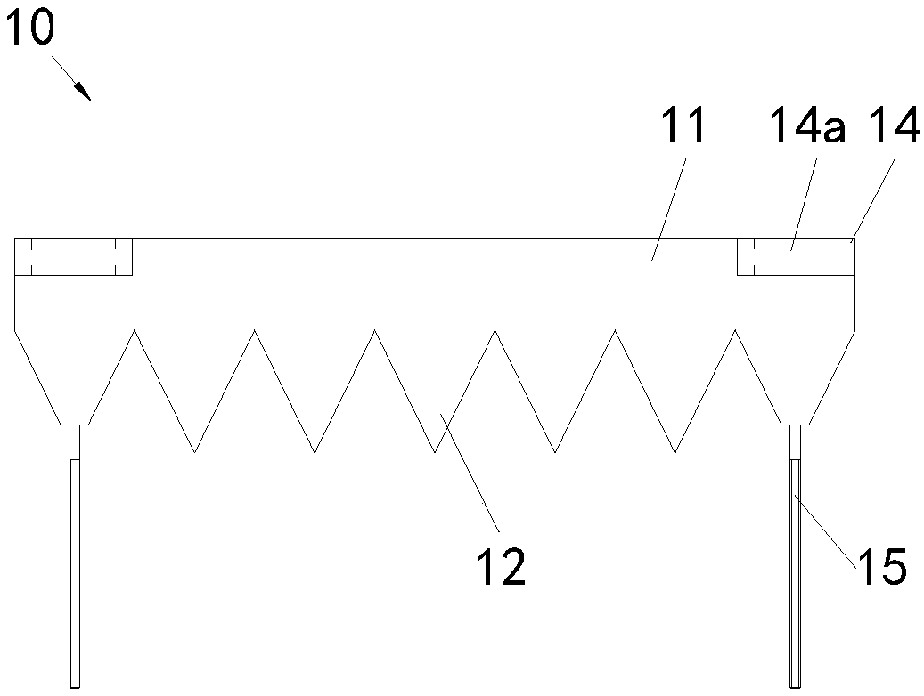
[0030] Example 1: Combining Figure 3 to Figure 9 To illustrate the tube straightening jig of the present invention, in order to clarify the direction relationship, an xyz rectangular coordinate system with the z-axis direction as the height extension direction of the tube straightening jig is set as required. It includes two staggered and oppositely arranged modules, namely the first module 10 and the second module 20; as image 3 and Figure 4 As shown, taking the first module 10 as an example to describe its specific structure in detail, it includes a strip-shaped base 11, the shape and size of which are arranged along the length direction of the base 11 are the same, and a number of sawtooth 12 arranged in a straight line , two screw rods-15 fixedly connected to the bottom of base-11 sawtooth-12 ends, and two positioning blocks-14 with through-holes-14a respectively fixed on the two ends of the side of base-11; Figure 5 As shown, the structure of the second module 20 is...

Embodiment 2

[0034] Embodiment 2: Combination Figure 3 to Figure 11 Illustrate the method for correcting planar tubes with the tube tube correction jig of the present invention, the specific steps are as follows:

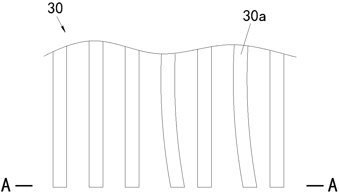
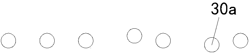
[0035] S1: if Figure 5 to Figure 7 As shown, assemble the jig for straightening tubes described in Embodiment 1, assemble the first module 10 and the second module 20 arranged up and down, and the saw teeth of the two modules are horizontally staggered and vertically opposite, the first module 10 The screw rod one 15 passes through the through hole two 24a of the positioning block two 24 of the second module 20 and is locked and fixed by a nut; The nuts are locked and fixed, and the screw rods respectively penetrate into the through holes of the opposite base and are tightened by the nuts. By tightening and loosening the nuts, the gap between the sawtooth of the two modules can be adjusted to adapt to the tube structure of different pipe diameters and gaps 30;

[0036] S2: i...


PUM


Abstract

The invention discloses a row tube correction clamp and a method thereof, and relates to the technical field of toolings and clamps. The row tube correction clamp and the method thereof are used for solving the problems that a row tube structure is corrected by manually applying external stress on tubes one by one, operation is tedious, the working efficiency is low, and the tube opening correction effect is poor. The row tube correction clamp comprises two modules which are arranged oppositely in a staggered mode. Each module comprises a long-strip-shaped base, a plurality of sawteeth arranged in the length direction of the base, two screws fixedly connected to the bottoms of the sawteeth at the two ends of the base, and two positioning blocks which are provided with through holes and fixedly connected to the two ends of the side surface of the base; and the screws penetrate through the positioning blocks of the opposite modules and are locked and fixed through nuts. The method comprises the steps that the row tube correction clamp is assembled; and the row tube correction clamp is arranged on a to-be-corrected portion of the row tube structure in a sleeving mode, the nuts are screwed up so as to close the two modules, the nuts continue to be screwed up, tubes are subjected to clamping force from the sawteeth of the two modules, and correction is achieved.

Description

technical field [0001] The invention relates to the technical field of tooling fixtures, in particular to a planar pipe alignment, welding correction fixture and a method thereof. Background technique [0002] In the petrochemical plant installation project, many equipment will have a planar tube structure, such as the water wall and superheater in the boiler system. Such as figure 1 and figure 2 As shown, since the diameter of each tube 30a of the tube array structure 30 is relatively small, individual tubes 30a are prone to bending and flatness deviation during transportation, which affects the subsequent grouping of the two tube array structures 30 and the alignment of the nozzles. For welding work, therefore, it is necessary to correct the pipe 30a that has been bent and deformed before implementing on-site counterpart welding work. [0003] At present, in the installation and construction site, to deal with the bending and deformation of the nozzles of the planar tu...

Claims


Application Information

Patent Timeline
Patent Type & Authority Applications(China)
IPC IPC(8): B23K37/053
Inventor 曹智云陆欢军倪志海李丰震孙纪军
Owner SHANGHAI INSTALLATION ENG GRP
Why Eureka
Try Eureka