Tree support for gardens

A garden and fixed shell technology, applied in the field of brackets, can solve the problems that cannot be reduced, cannot be corrected by saplings, and cannot be realized, so as to achieve the effects of improving buffer capacity, strengthening survival rate, and improving practicability

Inactive Publication Date: 2021-11-26
孙云飞
View PDF1 Cites 0 Cited by
  • Summary
  • Abstract
  • Description
  • Claims
  • Application Information

AI Technical Summary

Problems solved by technology

[0004] The device cannot achieve the purpose of correcting the growth direction of the trunk, cannot effectively correct the inclination of the saplings, cannot realize the function of protecting the bark, and cannot reduce the collision between the tree and the device during the growth process, which is likely to cause tree damage. damage, which reduces the survival rate of saplings. The device has a single structure and cannot realize the function of changing the support point of the fixed shell with the angle of inclination of the trunk.

Method used


Image

  • Tree support for gardens
  • Tree support for gardens
  • Tree support for gardens

Examples


Embodiment 1

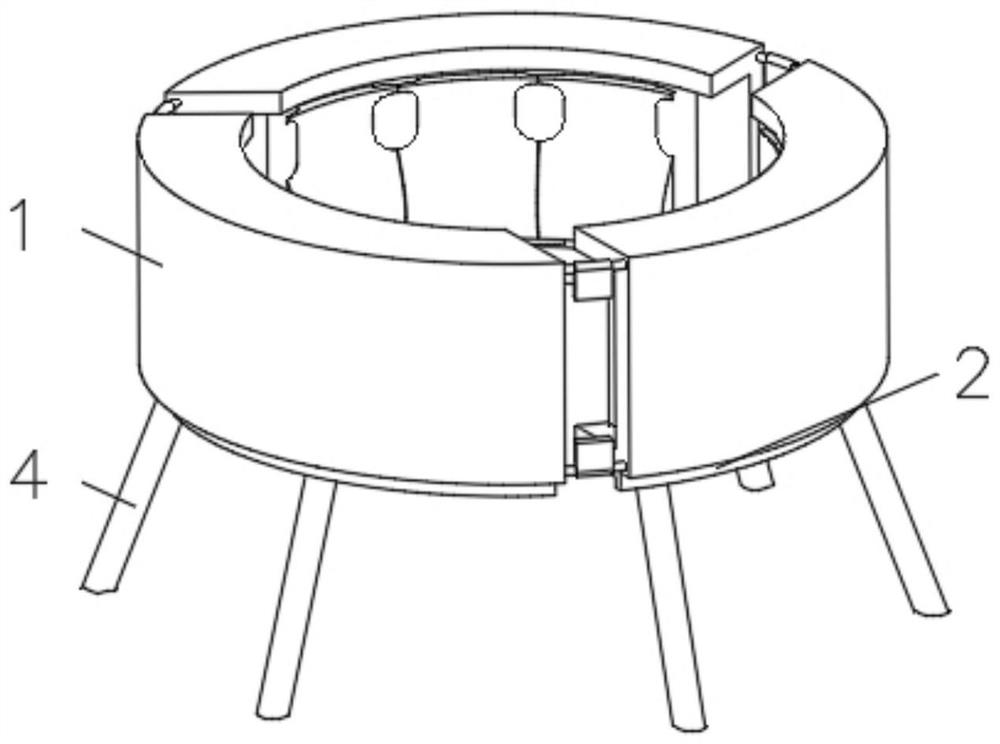
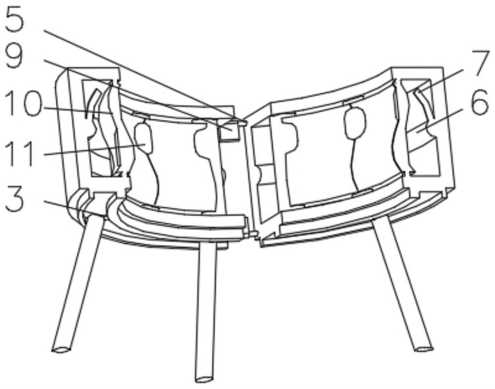
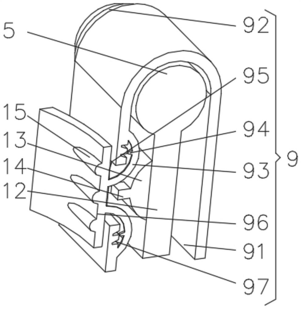
[0031] see Figure 1-4 , the present invention provides a technical solution: a tree support for gardens, including a fixed shell 1, the bottom of the fixed shell 1 is fixedly connected with an annular slide rail 2, the inner wall of the annular slide rail 2 is slidably connected with a sliding rod 3, and the sliding rod 3 A telescopic rod 4 is fixedly connected to one side of the fixed shell 1, and a connecting column 5 is movably connected between the fixed shells 1. The inner wall of the fixed shell 1 is fixedly connected with a soft rubber block 6, and the side of the soft rubber block 6 away from the fixed shell 1 is installed with an arc The rubber rod 7 is connected with an elastic block 8 at one end of the arc-shaped rubber rod 7 away from the soft rubber block 6 , and a correction device 9 is installed at one side of the connecting column 5 .

[0032] The rectifying device 9 includes a casing 91, a rolling bearing 92 runs through one side of the casing 91, the rolling...

Embodiment 2

[0036] see Figure 1-5 , the present invention provides a technical solution: on the basis of Embodiment 1, a protective device 10 is installed on the side of the fixed shell 1 close to the soft rubber block 6, the protective device 10 includes an outer frame 101, and the inner bottom of the outer frame 101 is fixedly connected There is a first spring 102, the end of the first spring 102 away from the outer frame 101 is fixedly connected with a top plate 103, the side of the top plate 103 away from the first spring 102 is installed with a first magnet block 104, and the side of the outer frame 101 is fixedly connected with an elastic force One end of the rope 105 and the elastic rope 105 is fixedly connected with a curved plate 106 , and the side of the curved plate 106 away from the elastic rope 105 is connected with a second magnet block 107 .

[0037] One side of the curved plate 106 is uniformly equipped with a rotating shaft 16 , one side of the rotating shaft 16 is equippe...

Embodiment 3

[0040] see Figure 1-6 , the present invention provides a technical solution: on the basis of the second embodiment, a buffer device 11 is installed on one side of the protection device 10, the buffer device 11 includes a device frame 111, and an elastic concave plate 112 is evenly installed on one side of the device frame 111 A circular limiting block 113 is fixedly connected to one side of the elastic concave plate 112 close to the device frame 111 .

[0041] A buffer block 114 is installed on the side of the elastic concave plate 112 away from the circular limit block 113 , and an extruding air bag 115 is installed inside the device frame 111 .

[0042] When in use, the trunk of the tree touches the buffer block 114 to squeeze the elastic concave plate 112 inwardly, so that the volume of the extruded airbag 115 increases after being squeezed, and pushes back the circular stopper 113 to make the elastic concave plate 112 protrude. Drive the buffer block 114 to contact the t...


PUM


Abstract

The invention discloses a tree support for gardens. The tree support comprises fixing shells, wherein annular sliding rails are fixedly connected to the bottoms of the fixing shells, sliding rods are slidably connected to the inner walls of the annular sliding rails, telescopic rods are fixedly connected to one sides of the sliding rods, connecting columns are movably connected between the fixing shells, rubber soft blocks are fixedly connected to the inner walls of the fixing shells, arc-shaped rubber rods are installed on the sides, away from the fixing shells, of the rubber soft blocks, elastic blocks are connected to the ends, away from the rubber soft blocks, of the arc-shaped rubber rods, correcting devices are installed on one sides of connecting columns, protecting devices are installed on the sides, close to the rubber soft blocks, of the fixing shells, a buffering device is installed on one side of each protection device, each correcting device comprises a shell, and a rolling bearing penetrates through one side of the shell. The invention relates to the technical field of supports. According to the tree support for the gardens, the purpose of correcting the growth direction of a tree trunk is achieved, inclination of a sapling is effectively corrected, and attractiveness of the sapling is guaranteed.

Description

technical field [0001] The invention relates to the technical field of brackets, in particular to a tree bracket for gardens. Background technique [0002] In urban greening construction, tree transplanting technology is widely used, which has the advantages of receiving good results in a short period of time and greatly speeding up the pace of urban greening construction. However, because the root system of the newly transplanted trees is not strong, the trees must be supported by a certain external force before they can grow upright. The more commonly used method at present is: support around the tree with wooden poles or metal poles, and use iron wires to tighten and reinforce the contact with the trunk. This method is simple and easy to do, but at the same time there are many disadvantages, such as the size is not adjustable, it is difficult to fit trees of different diameters, it is either too loose to support the original transplanted tree well, or it is too tight to ...

Claims


Application Information

Patent Timeline
Patent Type & Authority Applications(China)
IPC IPC(8): A01G17/14A01G7/06
CPCA01G17/14A01G7/06
Inventor 孙云飞
Owner 孙云飞
Why Eureka
Try Eureka