
Die with correcting function for shaft sleeve forging and correcting process thereof

A technology for forgings and functions, which is applied in the field of molds with correcting functions for shaft sleeve forgings and the field of correcting technology, which can solve the problems of small cutting allowance, low processing cost, and no correction for core rolls, and achieve good air tightness

Pending Publication Date: 2020-12-08
WUXI LONGDI PRECISED FORGINGS
View PDF7 Cites 0 Cited by
  • Summary
  • Abstract
  • Description
  • Claims
  • Application Information

AI Technical Summary

Problems solved by technology

[0004] A shaft sleeve forging mold structure disclosed in the Chinese invention patent application publication CN203401037U, the shaft sleeve forging mold structure, although a forging that is closer to the product shape is processed through the mold structure, the cutting allowance for subsequent processing is small, saving materials, The processing cost is low, and at the same time, the mold leaves a certain rolling space for forging processing, which ensures the quality and performance of the product. However, the forging mold structure of the shaft sleeve does not have the function of correcting the core roller

Method used


Image

  • Die with correcting function for shaft sleeve forging and correcting process thereof
  • Die with correcting function for shaft sleeve forging and correcting process thereof
  • Die with correcting function for shaft sleeve forging and correcting process thereof

Examples


Embodiment Construction

[0042] The following will clearly and completely describe the technical solutions in the embodiments of the present invention with reference to the accompanying drawings in the embodiments of the present invention. Obviously, the described embodiments are only some, not all, embodiments of the present invention.

[0043] In the description of the present invention, unless otherwise stated, the meaning of "plurality" is two or more; the terms "upper", "lower", "left", "right", "inner", "outer" , "front end", "rear end", "head", "tail", etc. indicate the orientation or positional relationship based on the orientation or positional relationship shown in the drawings, and are only for the convenience of describing the present invention and simplifying the description, rather than Nothing indicating or implying that a referenced device or element must have a particular orientation, be constructed, and operate in a particular orientation should therefore not be construed as limiting ...


PUM


Abstract

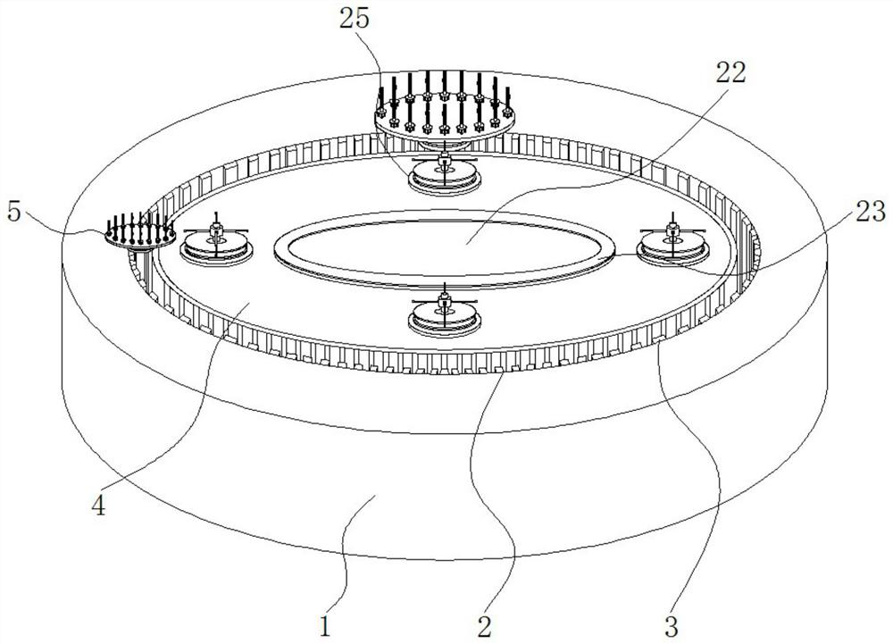
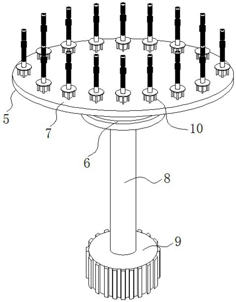
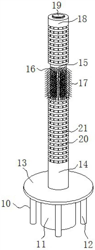
The invention discloses a die with a correcting function for a shaft sleeve forging and a correcting process thereof, and relates to the technical field of shaft sleeve forging dies. The die specifically comprises a base platform, a circular truncated cone, a core roller supporting mechanism, a core roller correcting device and main die clamping devices; an annular groove is formed in the base platform, and clamping teeth are fixed to the groove wall of one side of the annular groove; the circular truncated cone is fixed to the center of the inner side of the annular groove, the core roller supporting mechanism is installed between the base platform and the circular truncated cone and composed of a steering control disc, a tray, a supporting rod, a gear and the core roller correcting device, a surface grinding rotary disc is installed in the center of the upper surface of the circular truncated cone, and a dull polish ring is fixed to the edge of the upper surface of the surface grinding rotary disc; air grooves are evenly formed in the side wall of the circular truncated cone, and the main die clamping devices are arranged on the edge of the upper surface of the circular truncatedcone at equal intervals. According to the die with the correcting function for the shaft sleeve forging and the correcting process thereof, the upright degree of a core roller is corrected through the core roller correcting device, and the effect of stably clamping the core roller is achieved.

Description

technical field [0001] The invention relates to the technical field of forging molds for shaft sleeves, in particular to a mold with a straightening function for forging shaft sleeves and a straightening process. Background technique [0002] The shaft sleeve is an important part of contemporary mechanical equipment. Its main function is to support the mechanical rotating body, reduce the friction coefficient during its movement, and ensure its rotation accuracy. The bearings are mostly processed by forging, and they are also useful for injection molding. method, but in order to ensure the strength and hardness of bearing products, forged bearings have a wider range of applications. [0003] The use of molds is indispensable in the forging process. The molds can be quickly formed, and the use of molds for forging processing has the advantages of high precision and fast production. [0004] A shaft sleeve forging die structure is disclosed in the Chinese invention patent app...

Claims


Application Information

Patent Timeline
IPC IPC(8): B21J13/02B21J13/03B21J13/08B21J5/00B24B7/16B24B47/12
CPCB21J13/02B21J13/03B21J13/085B21J5/002B24B7/16B24B47/12Y02P70/10
Inventor 刘步蟾
Owner WUXI LONGDI PRECISED FORGINGS
Learn More