
Grain impact crushing tester

A technology of impact crushing and testing machines, which is applied in the direction of measuring devices, instruments, scientific instruments, etc., can solve the problems of fast wear of the hammer head and grate sieve, shutdown, easy blockage of grate sieve, etc., and contribute to energy-saving design , the effect of reducing interference

Pending Publication Date: 2018-01-23
FUJIAN UNIV OF TECH
View PDF11 Cites 6 Cited by
  • Summary
  • Abstract
  • Description
  • Claims
  • Application Information

AI Technical Summary

Problems solved by technology

The hammer crusher mainly relies on the impact force to complete the crushing operation. When the hammer crusher is working, the servo motor drives the rotor to rotate at a high speed, and the material enters the crusher cavity evenly. The high-speed rotating hammer head impacts, shears and tears At the same time, the gravity of the material itself makes the material rush from the high-speed rotating hammer head to the baffle plate and sieve bar in the frame body. A sieve plate is installed at the lower part of the rotor to crush particles smaller than the size of the sieve hole in the material. The first stage is discharged through the sieve plate, and the material larger than the sieve hole size is retained on the sieve plate and continues to be hit and ground by the hammer. The hammer head and grate screen of the traditional hammer crusher wear quickly, and the maintenance and balancing time is long. When crushing Hard materials wear faster. When crushing sticky and wet materials, it is easy to block the sieve gap of the grating bar, which is easy to cause downtime

Method used


Image

  • Grain impact crushing tester
  • Grain impact crushing tester
  • Grain impact crushing tester

Examples


Embodiment Construction

[0014] The following will clearly and completely describe the technical solutions in the embodiments of the present invention with reference to the accompanying drawings in the embodiments of the present invention. Obviously, the described embodiments are only some, not all, embodiments of the present invention. Based on the embodiments of the present invention, all other embodiments obtained by persons of ordinary skill in the art without making creative efforts belong to the protection scope of the present invention.

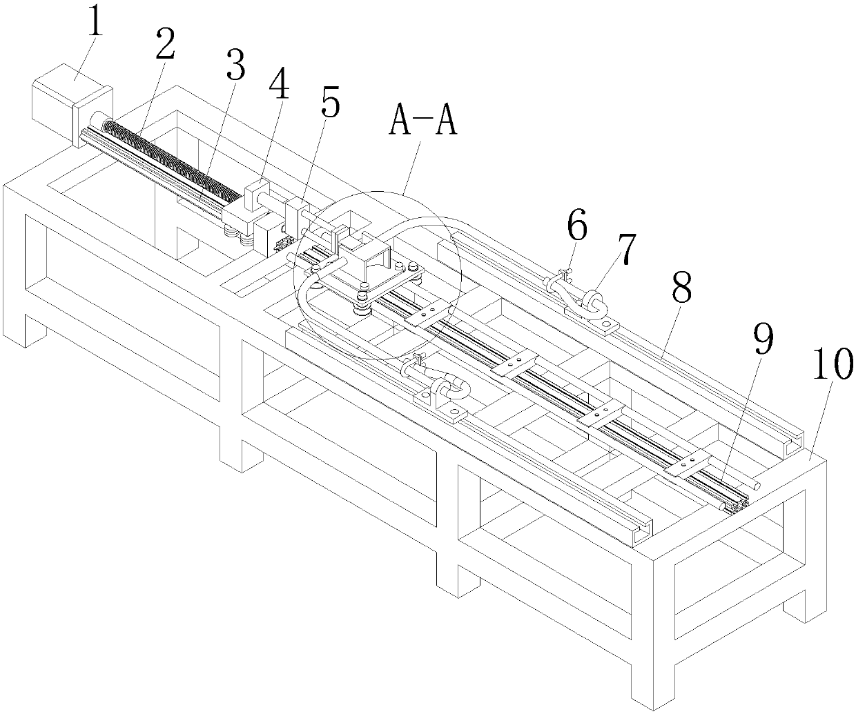
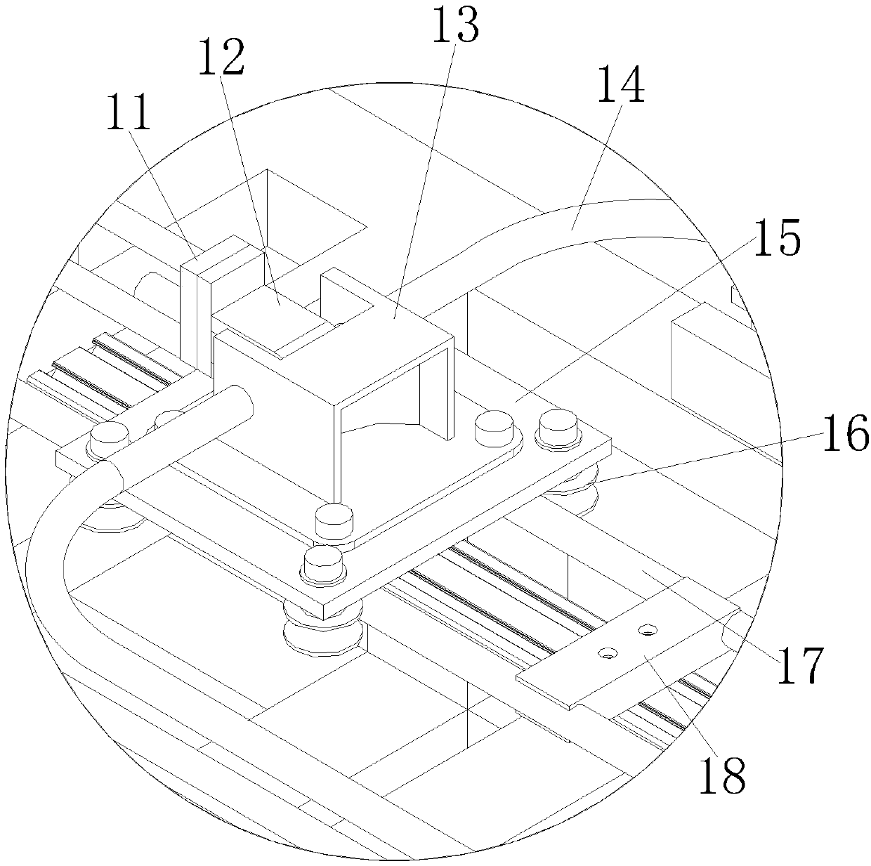
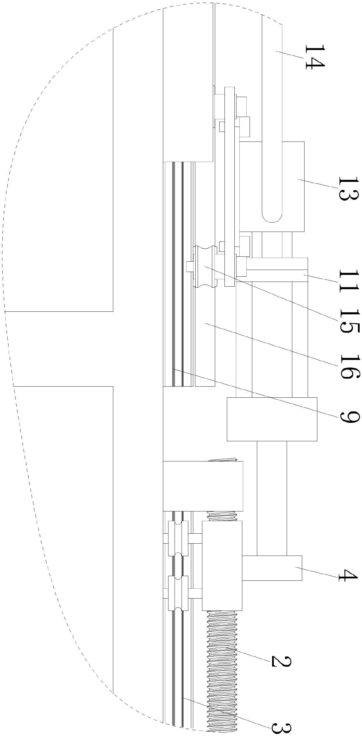
[0015] see Figure 1-3 , a particle impact crushing test machine, including a base 10, a servo motor 1 is installed on the base 10, a screw rod 2 is connected to the servo motor 1, a slide rail 3 is arranged on one side of the screw rod 2, and the screw rod 2 is far away from the servo motor One end of 1 is connected with tension device 4, and one side of tension device 4 is provided with load cell 5, and tension device 4 is connected with load cell 5, and one...


PUM


Abstract

The invention discloses a grain impact crushing tester which comprises a base, wherein a servo motor is arranged on the base; a screw rod is connected with the servo motor; a slide rail is arranged onone side of the screw rod; a tension device is connected with one end of the screw rod, away from the servo motor; a force measuring sensor is arranged on one side of the tension device; an electromagnet is arranged on one side of the force measuring sensor. The grain impact crushing tester disclosed by the invention is capable of driving the screw rod to rotate by the servo motor, so as to pulla pushing block connected with an elastic rope to move; when an elastic force detected by the force measuring sensor reaches a calibrated force, a signal is sent for automatically cutting off the electromagnet, so that grain impact crushing is realized; an impact crushing platform is capable of accurately controlling an impact crushing force, and meanwhile, the pushing block is capable of pushingthe grains for impact crushing without interference at the disconnecting moment through the connection of the electromagnet, so that uncertain factor interference is reduced; and the crushing effect can be judged by observing the grain crushing result.

Description

technical field [0001] The invention relates to the technical field of mechanical testing equipment, in particular to a particle impact crushing testing machine. Background technique [0002] The ore blocks are crushed by rapid impact, which can be divided into: hammer crusher, cage crusher, impact crusher, and vertical crusher. The hammer crusher mainly relies on the impact force to complete the crushing operation. When the hammer crusher is working, the servo motor drives the rotor to rotate at a high speed, and the material enters the crusher cavity evenly. The high-speed rotating hammer head impacts, shears and tears At the same time, the gravity of the material itself makes the material rush from the high-speed rotating hammer head to the baffle plate and sieve bar in the frame body. A sieve plate is installed at the lower part of the rotor to crush particles smaller than the size of the sieve hole in the material. The first stage is discharged through the sieve plate,...

Claims


Application Information

Patent Timeline
IPC IPC(8): G01N3/317
Inventor 李昆塬童昕余罗兼叶一青李占福凌静秀沈国浪夏辉煌
Owner FUJIAN UNIV OF TECH
Learn More