
Road construction pavement crushing device

A crushing device and road construction technology, applied in the direction of roads, roads, road repairs, etc., can solve the problems of long time consumption, energy waste, low crushing efficiency, etc., and achieve the effect of improving stability and increasing range

Inactive Publication Date: 2021-01-08
杨帮乐
View PDF0 Cites 1 Cited by
  • Summary
  • Abstract
  • Description
  • Claims
  • Application Information

AI Technical Summary

Problems solved by technology

[0003] During the use of existing road construction pavement crushing devices, the ground is generally crushed at a single point at a fixed point, and only one position is crushed at a time, resulting in the frequent movement of the crushing device for crushing, which is inefficient and time-consuming. Long, easy to cause energy waste

Method used


Image

  • Road construction pavement crushing device
  • Road construction pavement crushing device
  • Road construction pavement crushing device

Examples


Embodiment 1

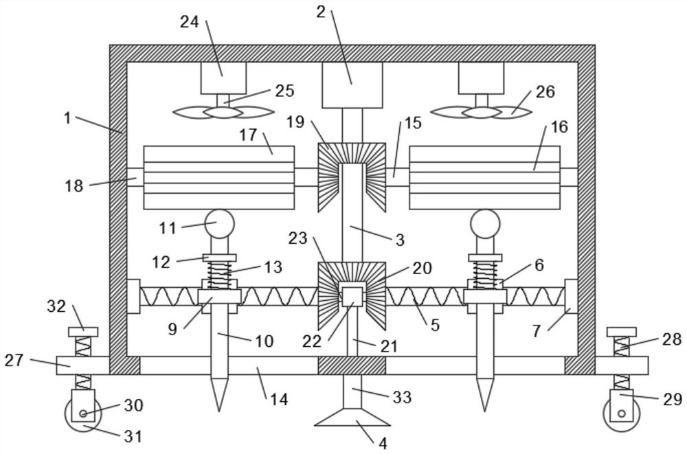
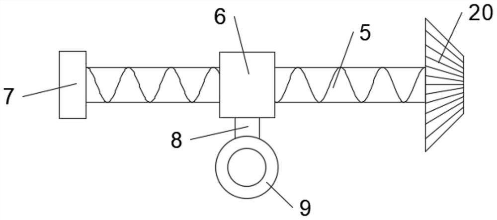
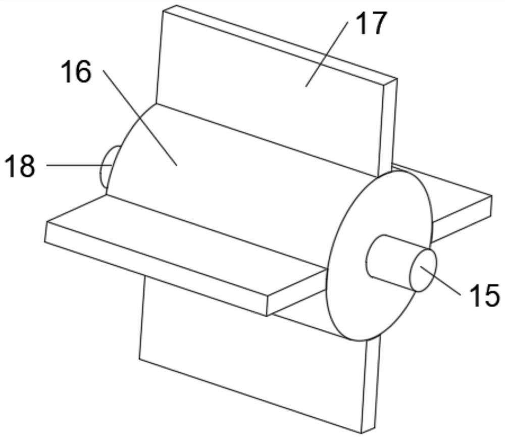
[0020] see Figure 1-3 , in an embodiment of the present invention, a road construction pavement crushing device includes a box body 1, a motor-2 is arranged on the inner top of the box body 1, and a shaft-3 is fixedly connected to the output end of the motor-2, and the shaft-3 There are a plurality of linkage devices on the upper side, the lower linkage device is fixedly connected with the screw rod 5, the slider 6 is slidably installed on the screw rod 5, the slider 6 is provided with an impact device, and the upper linkage device is fixedly connected with the driving device , start the motor one 2, make the shaft rod one 3 drive the driving device through the upper linkage device to drive the impact device, make it move downward, impact and break the ground, and the lower linkage device makes the screw rod 5 rotate, and then the slider 6 Drive the impact device to move left and right, so that the impact device moves left and right while crushing the ground, increasing the r...

Embodiment 2

[0028] In order to improve the stability of the device, this embodiment is further improved on the basis of Embodiment 1. The improvement is: the lower end of the box 1 is provided with a fixed rod 33, and the end of the fixed rod 33 is fixedly connected to the base 4. When the box body 1 is fixed at this position, the handle 32 can be rotated to rotate the screw rod 28 and drive the roller 31 to move upwards so that the base 4 touches the ground to prevent the roller 31 from rolling and cause the box body 1 to slide, thereby improving the stability of the device.

[0029] The working principle of this embodiment is: in order to improve the stability of the device, a fixed rod 33 is provided at the lower end of the box body 1, and the end of the fixed rod 33 is fixedly connected with the base 4, when the box body 1 needs to be fixed at this position , the handle 32 can be rotated to rotate the screw rod 28, and drive the roller 31 to move upward, so that the base 4 touches the ...


PUM


Abstract

The invention discloses a road construction pavement crushing device which comprises a box body, a motor I is arranged at the top end in the box body, a shaft rod I is fixedly connected to the outputend of the motor I, a plurality of linkage devices are arranged on the shaft rod I, a screw rod is fixedly connected to the linkage device below, a sliding block is slidably mounted on the screw rod,an impact device is arranged on the sliding block, and the linkage device at the upper part is fixedly connected with a driving device. By arranging the motor I, the first shaft rod drives a driving device through the linkage device at the upper part to drive the impact device to move downwards to impact and crush the ground, the linkage device at the lower part enables the screw rod to rotate, and then the sliding block drives the impact device to move leftwards and rightwards, so that the impact device crushes the ground while moving leftwards and rightwards, and the ground crushing range ofthe device is enlarged.

Description

technical field [0001] The invention relates to the field of road construction devices, in particular to a road construction pavement crushing device. Background technique [0002] Highway engineering refers to the investigation, measurement, design, construction, maintenance and management of highway structures. Highway engineering structures include: roadbeds, road surfaces, bridges, tunnels, tunnels, drainage systems, safety protection facilities, greening and traffic monitoring facilities. During road surface construction, the damaged road surface is usually broken to facilitate road surface repair. Re-repair, at this time a crushing device is needed to impact and crush the road surface. [0003] During the use of existing road construction pavement crushing devices, the ground is generally crushed at a single point at a fixed point, and only one position is crushed at a time, resulting in the frequent movement of the crushing device for crushing, which is inefficient a...

Claims


Application Information

Patent Timeline
IPC IPC(8): E01C23/12
CPCE01C23/12E01C23/122E01C23/124E01C2301/50
Inventor 杨帮乐
Owner 杨帮乐
Learn More