Backboard of backlight module

A backlight module and backplane technology, applied in optics, nonlinear optics, instruments, etc., can solve the problems of position shift of the optical diaphragm group, affecting the effect of liquid crystal display, etc., and achieve good wear resistance and long service life. , the effect of the simple method

Inactive Publication Date: 2018-01-23
HEFEI HUIKE JINYANG TECH
View PDF6 Cites 0 Cited by
  • Summary
  • Abstract
  • Description
  • Claims
  • Application Information

AI Technical Summary

Problems solved by technology

[0003] The purpose of the present invention is to provide a backlight module to solve the problem that in the existing backlight module, the position of the optical film group is easy to shift, which affects the effect of liquid crystal display

Method used


Image

  • Backboard of backlight module
  • Backboard of backlight module
  • Backboard of backlight module

Examples


Embodiment 1

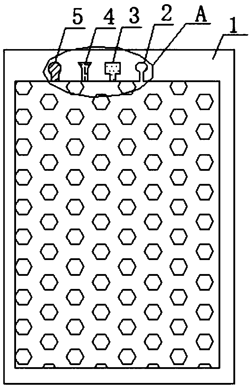
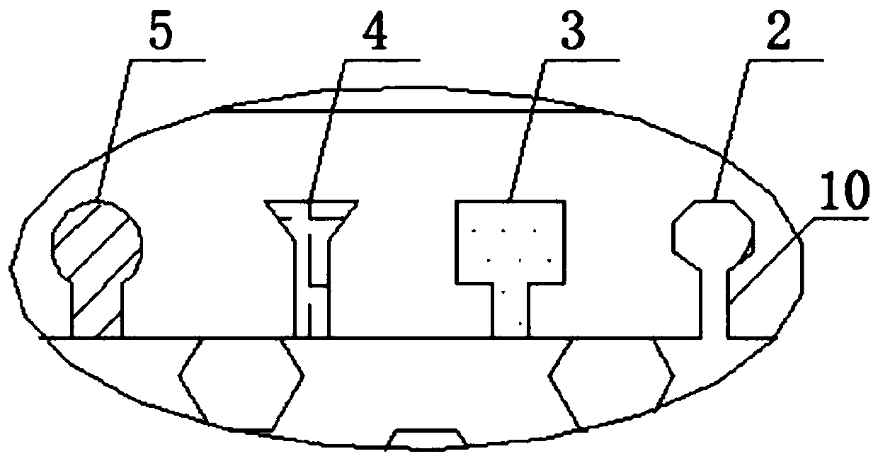
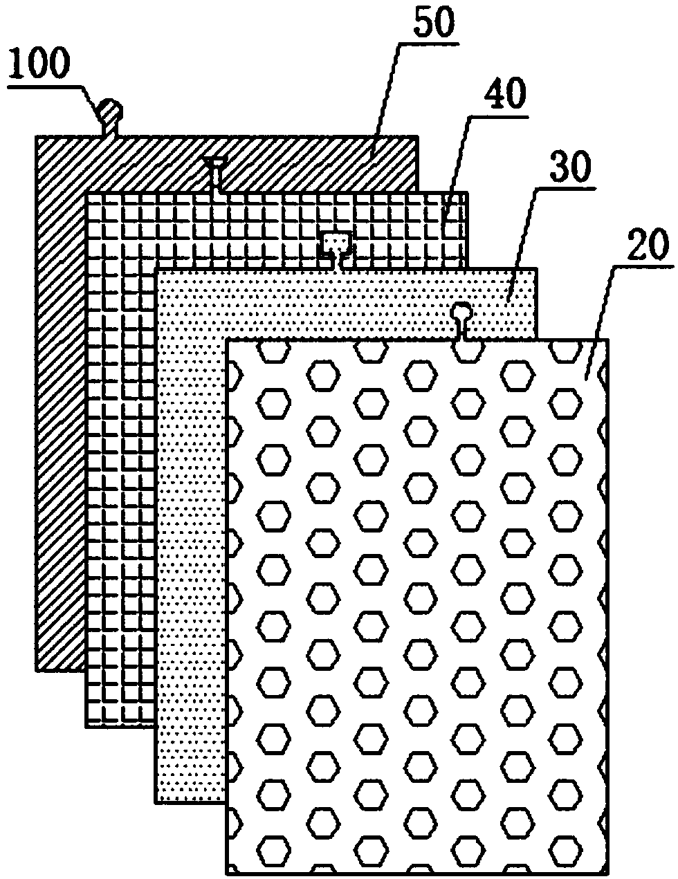
[0032] see Figure 1 to Figure 3 , the present invention provides a backlight module, including: a backplane 1, a first optical film 20, a second optical film 30, a third optical film 40, and a fourth optical film 50; An optical film placement groove is provided; the first optical film 20 , the second optical film 30 , the third optical film 40 and the fourth optical film 50 are stacked on the back plate 1 sequentially from top to bottom Inside; the inner end surface of the optical film placement groove is provided with the first positioning groove 2, the second positioning groove 3, the third positioning groove 4 and the fourth positioning groove 5 arranged in sequence; the first positioning groove 2 includes a strip Shaped extension 10 and a hexagonal positioning groove communicated with the striped extension 10; the second positioning groove 3 includes a striped extension 10 and a rectangular positioning groove communicated with the striped extension 10; The third position...

Embodiment 2

[0036] A method for manufacturing a backplane of a backlight module, the steps are as follows:

[0037] 1), structure and separate processing

[0038] There is an optical film placement groove on the back plate, and four optical films are stacked in the back plate from top to bottom; the inner end surface of the optical film placement groove is provided with a first positioning groove and a second positioning groove arranged in sequence , the third positioning groove and the fourth positioning groove; the first positioning groove includes a strip extension and a hexagonal positioning groove communicating with the strip extension; the second positioning groove includes a strip extension and a hexagonal positioning groove communicating with the strip extension The rectangular positioning groove; the third positioning groove includes a strip-shaped extension and a trapezoidal positioning groove communicated with the strip-shaped extension; the fourth positioning groove includes a...


PUM


Abstract

The invention relates to the technical field of display, in particular to a backboard of a backlight module. An optical film containing groove is formed in the backboard, and four optical films are sequentially arranged in the backboard in a stacked mode from top to bottom; a first positioning groove, a second positioning groove, a third positioning groove and a fourth positioning groove which aresequentially arranged are formed in the inner end face of the optical film containing groove; the first positioning groove comprises a strip-shaped extension part and a hexagonal positioning groove communicated with the strip-shaped extension part; the second positioning groove comprises a strip-shaped extension part and a rectangular positioning groove communicated with the strip-shaped extension part; the third positioning groove comprises a strip-shaped extension part and a trapezoidal positioning groove communicated with the strip-shaped extension part; the fourth positioning groove comprises a strip-shaped extension part and a circular positioning groove communicated with the strip-shaped extension part. According to the backboard of the backlight module and a manufacturing method ofthe backboard, the method is simple, and the manufactured backboard is long in service life and good in abrasion resistance.

Description

technical field [0001] The invention relates to the field of display technology, in particular to a backplane of a backlight module. Background technique [0002] Liquid crystal display is a flat and ultra-thin display device, which is composed of a certain number of color or black and white pixels, placed in front of the light source or reflective surface. Liquid crystal displays consume very little power, making them favored by engineers for electronic devices that run on batteries. Its main principle is to stimulate liquid crystal molecules with current to generate points, lines, and surfaces to form a picture with the back lamp tube. Existing liquid crystal displays usually include a backlight module and a liquid crystal panel. The backlight module is provided with an LED light and an optical film group. In the existing backlight module, the optical film group is prone to positional deviation, which affects the quality of the liquid crystal display. Effect. Contents ...

Claims


Application Information

Patent Timeline
IPC IPC(8): G02F1/13357
Inventor 白航空
Owner HEFEI HUIKE JINYANG TECH
Why Eureka
Try Eureka