Multi-functional cleaning and spin-drying device

A multi-functional, inner-cavity technology, applied in the direction of drying gas arrangement, drying, drying machine, etc., can solve the problems of reduced cleaning efficiency, single function, and the cleaning machine does not have a drying function, so as to reduce the use cost and prolong the service life. Service life, the effect of ensuring integrity

Inactive Publication Date: 2018-01-26
黄怀
0 Cites 2 Cited by

AI-Extracted Technical Summary

Problems solved by technology

[0003] The purpose of the present invention is to provide a multi-functional cleaning and drying device, which has the advantages of multiple functions, and...

Abstract

The invention discloses a multi-functional cleaning and spin-drying device which comprises a base, wherein deep grooves are formed in two sides of the bottom of the base; electric telescopic rods arefixedly connected with the tops of the inner cavities of the deep grooves; brackets are fixedly connected with the bottoms of the electric telescopic rods; the bottoms of the brackets extend out of the deep grooves; first rolling wheels are movably connected with the inner cavities of the brackets through rotating shafts; a tank body is fixedly connected with the top of the base; and sliding grooves are formed in the bottoms of two sides of the inner cavity of the tank body. Through the cooperative utilization of the base, the deep grooves, the electric telescopic rods, a rotating rod, the brackets, the first rolling wheels, the tank body, sliding rods, the sliding grooves, a moving plate, a fixing plate, the first motor, a disc, a cylinder, a motor case, a second motor, a rotating disc, afilter screen, a supporting plate, an air blower, an air outlet pipe and water outlet pipes, the multi-functional cleaning and spin-drying device has the advantages that a plurality of functions canbe achieved, and the problem that the cleaning efficiency is lowered because a conventional cleaning machine does not have the spin-drying function and is single in function can be solved.

Application Domain

Drying gas arrangementsCleaning using liquids

Technology Topic

EngineeringMultiple function +1

Image

  • Multi-functional cleaning and spin-drying device
  • Multi-functional cleaning and spin-drying device
  • Multi-functional cleaning and spin-drying device

Examples

  • Experimental program(1)

Example Embodiment

[0016] The technical solutions in the embodiments of the present invention will be clearly and completely described below in conjunction with the accompanying drawings in the embodiments of the present invention. Obviously, the described embodiments are only a part of the embodiments of the present invention, rather than all the embodiments. Based on the embodiments of the present invention, all other embodiments obtained by those of ordinary skill in the art without creative work shall fall within the protection scope of the present invention.
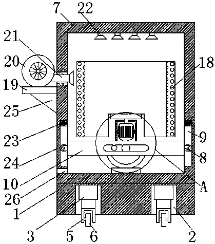
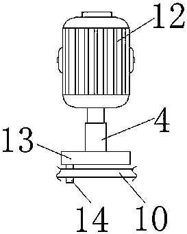
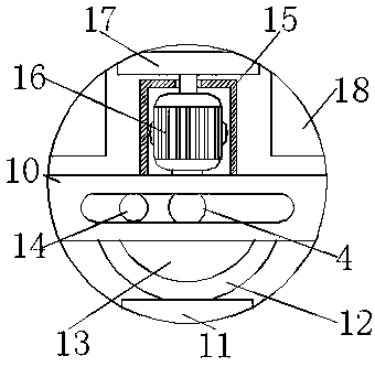
[0017] See Figure 1-3 , A multifunctional washing and drying device, comprising a base 1, both sides of the bottom of the base 1 are provided with deep grooves 2, the top of the inner cavity of the deep groove 2 is fixedly connected with an electric telescopic rod 3, and the bottom of the electric telescopic rod 3 is fixedly connected There is a bracket 5, the bottom of the bracket 5 extends to the outside of the deep groove 2, the inner cavity of the bracket 5 is movably connected with the first roller 6 through the rotating shaft, and the top of the base 1 is fixedly connected with the box body 7. There are chutes 9 at the bottom, and the top of the inner cavity of the chutes 9 is fixedly connected with a cushion 23. The cushion 23 is rectangular. The arrangement of the cushion 23 can prevent the sliding rod 8 and the chute 9 from colliding with each other, ensuring the chute The integrity of the chute 9 prolongs the service life of the chute 9 and reduces the use cost of the washing and drying device. The inside of the chute 9 is slidably connected with a sliding rod 8. The sliding rod 8 is located at one end of the inner cavity of the chute 9 and moves through the shaft A second roller 24 is connected. One end of the second roller 24 away from the sliding rod 8 is movably connected to the inner wall of the chute 9. By providing the second roller 24, the friction between the sliding rod 8 and the chute 9 is reduced. The sliding rod 8 and the sliding groove 9 can support the moving plate 10 in a balanced manner, facilitating the vertical movement of the moving plate 10. The sliding rod 8 is far away from the inner wall of the sliding groove 9 and located in the inner cavity of the box body 7, and the moving plate 10 is fixedly connected to the box. The bottom of the inner wall of the body 7 is fixedly connected with a fixing plate 11. By providing the fixing plate 11, the first motor 12 can be reinforced to make the first motor 12 more stable during operation. The top of the fixing plate 11 is fixedly connected with the first motor 12 Motor 12, the output end of the first motor 12 is fixedly connected with a rotating rod 4, the front of the rotating rod 4 is fixedly connected with a disc 13, and the left side of the surface of the disc 13 is fixedly connected with a cylinder 14, which is movably connected to the moving plate 10. Inside, the top of the moving board 10 is fixedly connected with a motor box 15, and the second motor 16 can be protected by setting the motor box 15. The top of the moving board 10 and located in the inner cavity of the motor box 15 is fixedly connected with the second motor 16, The output end of the second motor 16 is fixedly connected to the turntable 17, the inner cavity of the box 7 and located on the top of the turntable 17 is fixedly connected with a filter screen 18, the left side of the box 7 is fixedly connected with a support plate 19, and the bottom of the support plate 19 A tripod 25 is fixedly connected. The right side of the tripod 25 is fixedly connected to the left side of the box body 7. The support plate 19 is fixed by the setting of the tripod 25. The top of the support plate 19 is fixedly connected with a blower 20. The air outlet is connected with an air outlet pipe 21. The right end of the air outlet pipe 21 penetrates the box body 7 and extends to the inside of the box body 7. The top of the inner cavity of the box body 7 and the top of the filter screen 18 communicate with the top of the box body 7 The number of outlet pipes 22 is not less than four, and the outlet pipes 22 are arranged at equal distances. The bottom of the left side of the inner wall of the box 7 is provided with a water outlet 26, which passes through the base 1, the deep groove 2, and the electric telescopic Rod 3, rotating rod 4, bracket 5, first roller 6, box body 7, sliding rod 8, chute 9, moving plate 10, fixed plate 11, first motor 12, disc 13, cylinder 14, motor box 15 , The second motor 16, turntable 17, filter 18, support plate 19. The combined use of the blower 20, the air outlet pipe 21 and the water outlet pipe 22 has the advantage of multi-function, which solves the problem that the existing washing machine does not have a drying function and has a single function, thereby reducing the cleaning efficiency.
[0018] When in use, the user opens the water outlet 22 to make the water flow into the box 7, and the external controller turns on the first motor 12 to move. The first motor 12 drives the rotating rod 4 to rotate, and the rotating rod 4 drives the disc 13 to rotate. Drive the cylinder 14 to rotate, the cylinder 14 drives the moving plate 10 to move, the moving plate 10 drives the sliding rod 8 to slide in the chute 9, the user turns on the second motor 16 to move through the external controller, and the second motor 16 drives the turntable 13 to rotate up and down , The turntable 13 drives the filter screen 18 to rotate, and the second motor 16, the turntable 17, and the filter screen 18 move up and down through the cooperation of the sliding rod 8, the sliding groove 9, the moving plate 10, the first motor 12, the disc 13, and the cylinder 14. After cleaning, the water flows out from the water outlet 26, the operator turns on the blower 20 through the controller, and the blower 20 rotates to blow the wind into the inner cavity of the box body 7 to dry the articles.
[0019] To sum up: the multifunctional washing and drying device passes through the rotating rod 4, the box body 7, the sliding rod 8, the sliding groove 9, the moving plate 10, the fixed plate 11, the first motor 12, the disc 13, the cylinder 14, The cooperation of the second motor 16, the turntable 17, the filter screen 18, the blower 20, the water outlet pipe 22 and the water outlet hole 26 solves the problem that the existing washing machine does not have a drying function and has a single function, thereby reducing the cleaning efficiency.
[0020] Although the embodiments of the present invention have been shown and described, those of ordinary skill in the art can understand that various changes, modifications, and substitutions can be made to these embodiments without departing from the principle and spirit of the present invention. And variations, the scope of the present invention is defined by the appended claims and their equivalents.

PUM

no PUM

Description & Claims & Application Information

We can also present the details of the Description, Claims and Application information to help users get a comprehensive understanding of the technical details of the patent, such as background art, summary of invention, brief description of drawings, description of embodiments, and other original content. On the other hand, users can also determine the specific scope of protection of the technology through the list of claims; as well as understand the changes in the life cycle of the technology with the presentation of the patent timeline. Login to view more.

Similar technology patents

Method and system for detecting industrial fault

ActiveCN107544464AIntegrity guaranteedGood collection effect
Owner:天津达芸科技有限公司

Directionally degradable and absorbable magnesium bone screw and preparation method thereof

ActiveCN105056309AIntegrity guaranteedMaintain early fastening force
Owner:SUZHOU ORIGIN MEDICAL TECH

Classification and recommendation of technical efficacy words

  • Integrity guaranteed
  • Extended service life

Image acquisition method and image acquisition device

InactiveCN103139480AIntegrity guaranteedImprove photo efficiency
Owner:HUAWEI DEVICE CO LTD

Method, client side and system for broadcasting media fragmentations in turn

InactiveCN103685264AIntegrity guaranteedwaste of processing resources
Owner:LE SHI ZHI XIN ELECTRONICS TECH TIANJIN

Digital value acquisition circuit with fault diagnosis capacity

ActiveCN102916689AImprove self-diagnosis coverageIntegrity guaranteed
Owner:CHINA TECHENERGY +1

Method for safely and flexibly upgrading firmware

InactiveCN103207800AImprove upgrade securityIntegrity guaranteed
Owner:XIAMEN YEALINK NETWORK TECH

Fracturing manifold quick connecting device

Owner:YANTAI JEREH PETROLEUM EQUIP & TECH

Modified asphalt composition with creeping characteristic and preparation method thereof

InactiveCN102020859Aavoid rapid agingExtended service life
Owner:ZHEJIANG WOPUMAN HIGH NEW MATERIALS
Why Eureka
Try Eureka