Device and method for measuring flank wear of ball end milling cutter

A ball-nose milling cutter and measuring device technology, which is applied in the direction of measuring/indicating equipment, metal processing machinery parts, metal processing equipment, etc., can solve the problems that affect the milling precision tool life, the measurement accuracy cannot be guaranteed, and the flank structure is complicated. , to achieve the effect of simple and feasible method, shortened measurement time and high authenticity

Inactive Publication Date: 2018-01-26
HARBIN UNIV OF SCI & TECH
View PDF5 Cites 14 Cited by
  • Summary
  • Abstract
  • Description
  • Claims
  • Application Information

AI Technical Summary

Problems solved by technology

There are a large number of complex structures such as grooves, rounded corners, and convex-concaves in the mold during processing. At the same time, overall wear and damage will occur during the processing. Severe tool wear will also cause cutting chatter, which will affect milling accuracy and tool life.
At present, the resear

Method used


Image

  • Device and method for measuring flank wear of ball end milling cutter
  • Device and method for measuring flank wear of ball end milling cutter
  • Device and method for measuring flank wear of ball end milling cutter

Examples


Embodiment 1

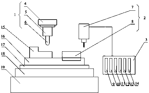
[0028] A ball end milling cutter flank wear measuring device, which consists of: hardware and software parts, the hardware includes: processing device 1, re-image device 2 and tablet computer 3 three parts, the tablet computer is equipped with special Three-coordinate measurement software, tool wear measurement software and windows system, the processing device includes a frame 4, the frame is connected to the main shaft 5, the main shaft is connected to the ball end milling cutter 6, and the re-imaging device It includes a three-coordinate measuring instrument 7 and a re-image board 8, and the three-coordinate measuring instrument is connected to a tablet computer.

Embodiment 2

[0030] According to the ball end milling cutter flank wear measuring device described in Embodiment 1, the ball end milling cutter is connected with the closed milling machine spindle, and a workpiece 15 is placed under it, and the workpiece connection fixture 16, the The clamp is fixed on the connecting plate 17 , the connecting plate is installed on the fixing block 18 , and the fixing block is installed on the base 19 .

Embodiment 3

[0032] According to the ball end milling cutter flank wear measuring device described in embodiment 1 or 2, a mirror plate is placed under the three-coordinate measuring instrument, the mirror plate is connected to a fixture, and the fixture is fixed on the connection The connecting plate is installed on the fixed block, and the fixed block is installed on the base.


PUM


Abstract

The invention relates to a device and method for measuring flank wear of a ball end milling cutter. With the progress of the machine manufacturing technology, in the milling process, the requirementsfor the machining precision of workpieces are higher increasingly. At the same time, due to the special double helix structure of the ball end milling cutter, it is necessary to study flank wear of the milling cutter so as to improve the surface machining quality. The device for measuring flank wear of the ball end milling cutter comprises two parts of hardware and software, wherein the hardware comprises a machining device (1), a double-reflection device (2) and a tablet computer (3), wherein the machining device comprises a machine frame (4). The machine frame is connected with a main shaft(5), and the main shaft is connected with a milling cutter (6), and the double-reflection device comprises a three-coordinate measuring instrument (7) and a double-reflection plate (8). The three-coordinate measuring instrument is connected with the tablet computer, and three-coordinate measuring software, tool wear measurement software and a windows system are installed on the tablet computer. The device and method are used for accurate measurement of flank wear when the milling cutter conducts milling.

Description

technical field [0001] The invention relates to a measuring device and a measuring method for the flank wear of a ball-end milling cutter, in particular to a measuring method for the flank wear of a milling cutter in the milling process using a ball-end milling cutter, and belongs to the technical field of mechanical cutting. Background technique [0002] With the continuous development of mechanical manufacturing technology, the complexity of the workpiece is gradually increasing in metal cutting. There are a large number of complex structures such as grooves, rounded corners, and convex-concaves in the mold during processing. At the same time, overall wear and damage will occur during the processing. Severe tool wear will also cause cutting chatter, which will affect milling accuracy and tool life. . At present, the research on tool wear detection technology is mainly concentrated in the field of turning, but there are not many researches in the field of milling. Due to t...

Claims


Application Information

Patent Timeline
IPC IPC(8): B23Q17/09
Inventor 岳彩旭朱磊
Owner HARBIN UNIV OF SCI & TECH
Why Eureka
Try Eureka