Control mechanism for seal water valve and seal water valve

A control mechanism and sealing water technology, which is applied to the valve shell structure, sliding valve, valve details, etc., can solve the problems of complex structure, short service life, and short life of the sealing water valve, and achieve improved sealing stability and service life. The effect of avoiding leakage problems and prolonging the service life

Pending Publication Date: 2018-01-26
XINHUA XINYUAN ELECTRONICS CERAMICS CO LTD
View PDF5 Cites 6 Cited by
  • Summary
  • Abstract
  • Description
  • Claims
  • Application Information

AI Technical Summary

Problems solved by technology

[0004] The invention provides a control mechanism and a sealing water valve for sealing water valves to solve the technical problems of the existing sealing water valves with complex structure, short service life and short life, and easy to cause water leakage

Method used


Image

  • Control mechanism for seal water valve and seal water valve
  • Control mechanism for seal water valve and seal water valve
  • Control mechanism for seal water valve and seal water valve

Examples


Embodiment Construction

[0027] The embodiments of the present invention will be described in detail below with reference to the accompanying drawings, but the present invention can be implemented in various ways defined and covered below.

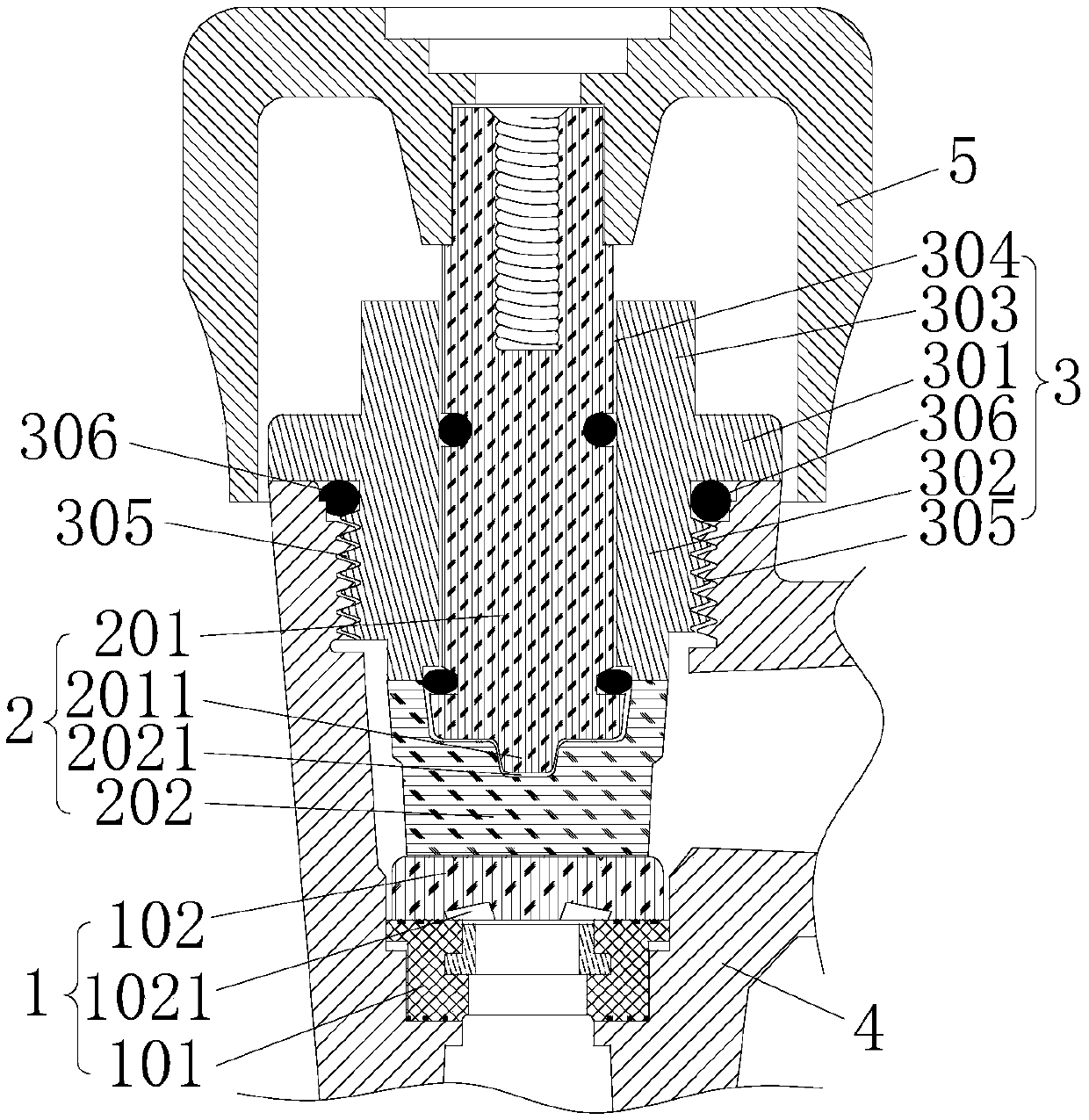
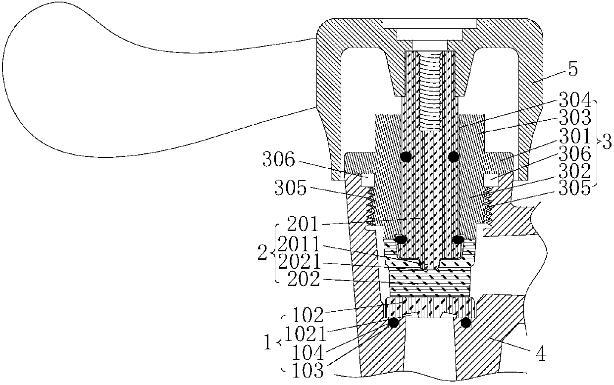
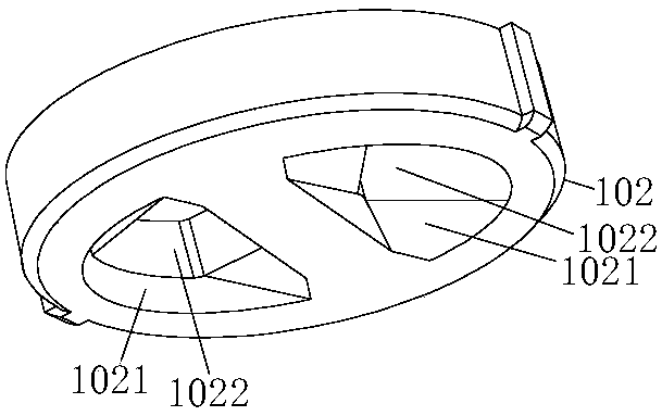
[0028] figure 1 It is one of the structural schematic diagrams of the control mechanism for the sealing water valve in the preferred embodiment of the present invention; figure 2 It is the second structural diagram of the control mechanism for the sealing water valve in the preferred embodiment of the present invention; image 3 It is one of the structural schematic diagrams of the static sheet of the preferred embodiment of the present invention; Figure 4 It is the second structural diagram of the static sheet of the preferred embodiment of the present invention; Figure 5 is a structural schematic diagram of a fastener in a preferred embodiment of the present invention; Figure 6 It is one of the structural schematic diagrams of the moving piece in the pref...


PUM


Abstract

The invention discloses a control mechanism for a seal water valve and the seal water valve. The control mechanism for the seal water valve comprises a stator blade mechanism fixedly sealed and covered on a water inlet or a water outlet of a valve inner cavity of the seal water valve and used for forming a fixed circulation channel, a rotor plate mechanism used for forming a movable circulation channel and fit to and rotatably matched with the stator blade mechanism so as to control a water flow amount, and a fastening piece used for sealing an assembly port of a sealed and covered valve bodyand compressing and fitting the rotor plate mechanism onto the stator blade mechanism along an axial direction so as to form axial fastening and positioning. Compression-fit seal between the fasteningpiece and the rotor plate mechanism and compression-fit seal between the rotor plate mechanism and the stator blade mechanism form a double-layer dynamic seal structure. The whole structure is simple, seal links are less, all dynamic seal contacting a water flow adopts binding faces with mirror surface brightness levels for compression-fit seal, and the leakage problem brought by the wear duringa rotation process can be effectively avoided, so that the service life of the whole seal water valve is prolonged.

Description

technical field [0001] The invention relates to the technical field of water valve structures, in particular to a control mechanism for sealing water valves. In addition, the present invention also relates to a sealing water valve comprising the above-mentioned control mechanism for the sealing water valve. Background technique [0002] Angle valves and faucets are all existing household sealed water valves commonly used, and the water flow control part often adopts a spool mechanism. The structure of the existing spool mechanism is complicated, including the valve sleeve, valve stem, moving piece, static piece, sealing ring and other auxiliary structures. It is necessary to carry out double-layer waterproof and leak-proof inside the spool mechanism and between the spool mechanism and the valve body. Measures, and the double-layer waterproof and leak-proof measures will be exposed to the water flow erosion of the inner cavity of the valve body. Once there is leakage in one ...

Claims


Application Information

Patent Timeline
Patent Type & Authority Applications(China)
IPC IPC(8): F16K3/08F16K3/02F16K3/314F16K27/04
Inventor 张南新
Owner XINHUA XINYUAN ELECTRONICS CERAMICS CO LTD
Why Eureka
Try Eureka