A method for measuring surface defects of linear guide rail

A technology for linear guides and defects, which is applied in the field of measuring concave and convex defects on the surface of linear guides, can solve problems such as difficulty in repairing, difficulty in determining accurate positions, etc., and achieves the effects of simple and reasonable method, elimination of errors, and improvement of detection efficiency.

Active Publication Date: 2020-04-17
浙江双鸿科技有限公司 +2
View PDF6 Cites 0 Cited by
  • Summary
  • Abstract
  • Description
  • Claims
  • Application Information

AI Technical Summary

Problems solved by technology

[0003] In order to solve the technical problem in the prior art that it is difficult to determine the exact position of the surface defect measurement of the linear guide rail based on the laser interferometer and bring difficulties to the repair, the present invention provides a method for measuring the surface defect of the linear guide rail, which can detect the position of the surface defect of the linear guide rail accurately. Provide accurate basis for repairing surface defects of linear guide rails

Method used


Image

  • A method for measuring surface defects of linear guide rail
  • A method for measuring surface defects of linear guide rail
  • A method for measuring surface defects of linear guide rail

Examples


Embodiment 1

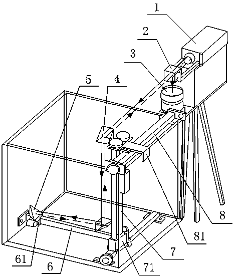
[0015] Such as figure 1 As shown, a method for measuring surface defects of a linear guide rail includes a laser interferometer 1 , a beam splitter 2 , a camera 3 , a 45-degree right-angle prism 4 and a corner cube 5 . The measured X guide rail 8 is fixed on the right side of the upper end surface of the radiotherapy water tank. The measured X guide rail 8 is movably socketed on the X carrier 81 . The X stage 81 is fixed with the Y guide rail 7 to be tested. The upper end of the tested Y guide rail 7 is fixed to the X carrier 81, and the lower end extends into the bottom of the inner cavity of the radiotherapy water tank. The measured Y guide rail 7 is movably socketed on the Y carrier platform 71 . The Z guide rail to be tested is fixed on the Y stage 71 . The Z guide rail under test is socketed on the Z stage 61 . The Z stage 61 is connected to the scanning probe base (not shown in the figure). figure 1 In the figure, the left end of the figure is the original point of...


PUM


Abstract

The invention provides a linear guide rail surface defect measurement method and relates to the test technology field. According to the method, a pyramid prism moves to acquire linear guide rail scaledisplacement d of a guide rail surface defect, a light beam emitted by a laser interferometer is reflected by the pyramid prism to return along an original path, after light splitting, one light beamis incident to the laser interferometer to acquire interferometer detection displacement l of the guide rail surface defect, another light beam is incident to a camera, light spot conversion is formed through a CCD photosurface, an actual distance s of the pyramid prism in the guide rail surface defect is acquired through calculation, and an actual distance L of the guide rail surface defect is equal to sum of the l and the s. The method is advantaged in that a technical problem of restoration difficulty because of difficulty in position determination during measurement of the linear guide rail surface detect existing in a laser interferometer in the prior art is solved, the error of utilizing the laser interferometer for measurement is eliminated, measurement is more accurate, and accurate basis is provided for restoration of the linear guide rail surface defect.

Description

technical field [0001] The invention relates to the technical field of testing, in particular to a method for measuring concave-convex defects on the surface of a linear guide rail based on a laser interferometer. Background technique [0002] Radiation therapy for tumors is very important for the quality control of radiation therapy equipment. At present, the structure of radiotherapy equipment in most hospitals is as follows: the 3D scanning system is installed in the water tank, the X linear guide rail of the 3D scanning system is horizontally fixed on the upper end of the water tank, and the Y linear guide rail passes through the slidable first slider and the X linear guide rail. Connection, the Z linear guide rail is connected with the Y linear guide rail through the slidable second slider, the Y linear guide rail and the Z linear guide rail fall into the water tank, the scanning probe is installed on the rotating seat, and the rotating seat is connected to the Y linear...

Claims


Application Information

Patent Timeline
Patent Type & Authority Patents(China)
IPC IPC(8): G01B11/00G01B11/27
Inventor 许照乾孔明李云鹏赵军刘维王道档单良
Owner 浙江双鸿科技有限公司
Why Eureka
Try Eureka