
Machine-vision image recognition and positioning method

A machine vision and image recognition technology, applied in image analysis, image data processing, instruments, etc., can solve problems affecting the accuracy of machine vision system recognition, product missing recognition or repeated recognition output, etc.

Inactive Publication Date: 2018-01-26
LOTES SHENZHEN
View PDF5 Cites 7 Cited by
  • Summary
  • Abstract
  • Description
  • Claims
  • Application Information

AI Technical Summary

Problems solved by technology

[0003] The machine vision system currently used in the automated production line generally uses the automatic control system to control the industrial camera to take pictures at a set time interval, and the machine vision system processing software processes the received image data to identify the products on the automated production line. However, due to factors such as the position of the light source, the geometric shape of the object, the surface texture, and the sudden change in the speed of the automated production line, the accuracy of the machine vision system's recognition will be affected, resulting in the frequent occurrence of missing or repeated recognition of the product by the machine vision system.

Method used


Image

  • Machine-vision image recognition and positioning method
  • Machine-vision image recognition and positioning method
  • Machine-vision image recognition and positioning method

Examples


Embodiment Construction

[0033] In order to facilitate a better understanding of the purpose, structure, features, and effects of the present invention, the present invention will now be further described in conjunction with the accompanying drawings and specific embodiments.

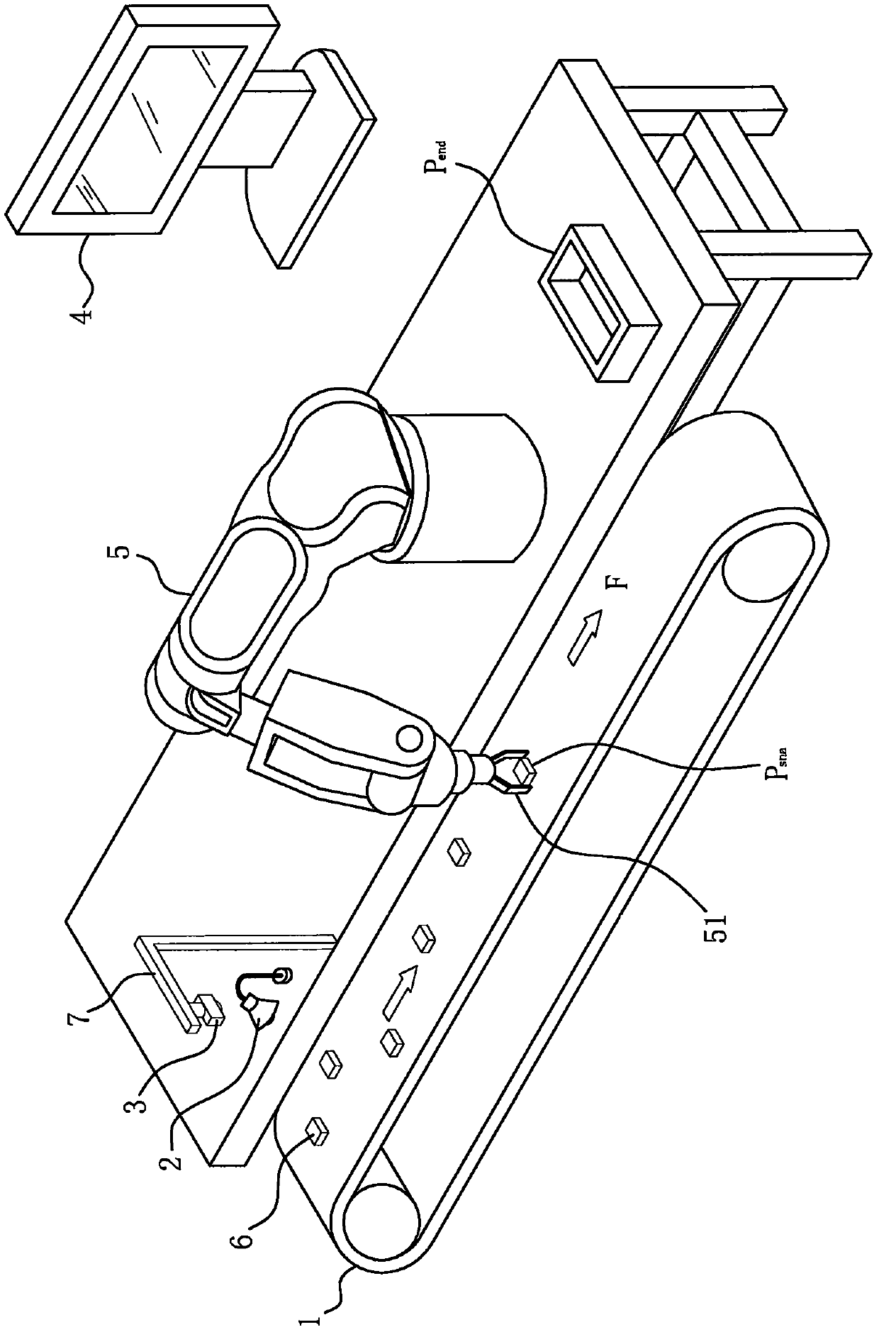
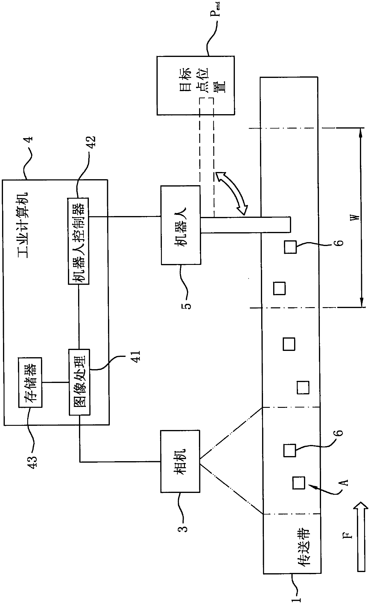
[0034] see figure 1 and figure 2 , the present invention is applied to a grabbing system for a target workpiece on a conveyor belt. The grabbing system includes: a conveyor belt 1 , a light source 2 , a camera 3 , an industrial computer 4 , a robot 5 and a target workpiece 6 . The robot 5 is a six-degree-of-freedom robot, and is installed at one end of the conveyor belt 1. An end effector 51 is installed on the end flange of the robot 5. In this embodiment, the end effector 51 is a gripper. The camera 3 is installed on the camera bracket 7 at one end of the conveyor belt 1 , and the camera 3 is located upstream of the robot 5 and vertically faces the target workpiece 6 on the conveyor belt 1 . The light source 2 is installed...


PUM


Abstract

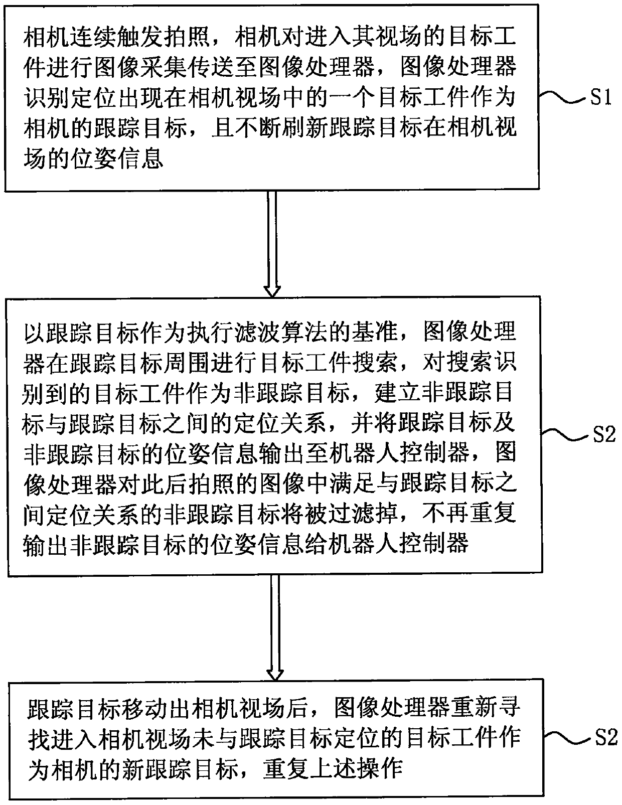
The invention discloses a machine-vision image recognition and positioning method. A tracked target is selected in a camera view field through an image processor; the tracked target is used as a reference of executing a filtering algorithm to carry out target workpiece searching around the tracked target; a target workpiece obtained by searching and recognition is used as a non-tracked target to establish a positioning relationship between the non-tracked target and the tracked target, and position and pose information of the tracked target and the non-tracked target is output to a robot controller at the same time; then the non-tracked target which is in shot images and meets the positioning relationship with the tracked target can be filtered out by the image processor; and the positionand pose information of the non-tracked target is no longer repeatedly output to the robot controller, repeatedly outputting the same target workpiece to the robot controller is avoided, then carryingout calculation of repeated forecasting of to-be-grasped position of the same target workpiece and the like by the robot controller and carrying out repeated grasping movement by a robot are avoided,and a target workpiece entering a side of the camera view field can also be recognized and positioned.

Description

【Technical field】 [0001] The invention relates to an image recognition and positioning technology, in particular to a machine vision image recognition and positioning method for identifying and positioning a target workpiece on a conveyor belt. 【Background technique】 [0002] The machine vision system has the advantages of high precision, good continuity, and strong flexibility. It is an effective way to realize precise control, intelligence, and automation of instruments and equipment. Therefore, in modern industrial automation production, machine vision is widely used in various In the application of inspection, production monitoring and parts identification, such as dimensional inspection of batch processing of spare parts, integrity inspection of automatic assembly, automatic positioning of components in electronic assembly lines, positioning guidance of industrial robots, etc. [0003] The machine vision system currently used in the automated production line generally u...

Claims


Application Information

Patent Timeline
Patent Type & Authority Applications(China)
IPC IPC(8): G06T7/00G06T7/292
Inventor 陈晨张志青曹学东
Owner LOTES SHENZHEN
Learn More