
Automatic lock nut machine

A nut machine and automatic lock technology, applied in metal processing, metal processing equipment, manufacturing tools, etc., to achieve positioning, avoid no-load phenomenon, and improve accuracy

Active Publication Date: 2018-06-22
JIANGSU BOZHIWANG AUTOMATION EQUIP CO LTD
View PDF5 Cites 0 Cited by
  • Summary
  • Abstract
  • Description
  • Claims
  • Application Information

AI Technical Summary

Problems solved by technology

[0004] The main purpose of the present invention is to overcome the defects of existing manual nut screwing, and provide an automatic lock nut machine, so as to realize the full automation of loading, screwing nuts, and blanking, and further improve work efficiency, so that it is more suitable for Practical and has industrial utilization value

Method used


Image

  • Automatic lock nut machine
  • Automatic lock nut machine
  • Automatic lock nut machine

Examples


Embodiment Construction

[0050] In order to further explain the technical means and effects of the present invention to achieve the intended purpose of the invention, the specific implementation, features and effects of the automatic nut locking machine proposed according to the present invention are described in detail below.

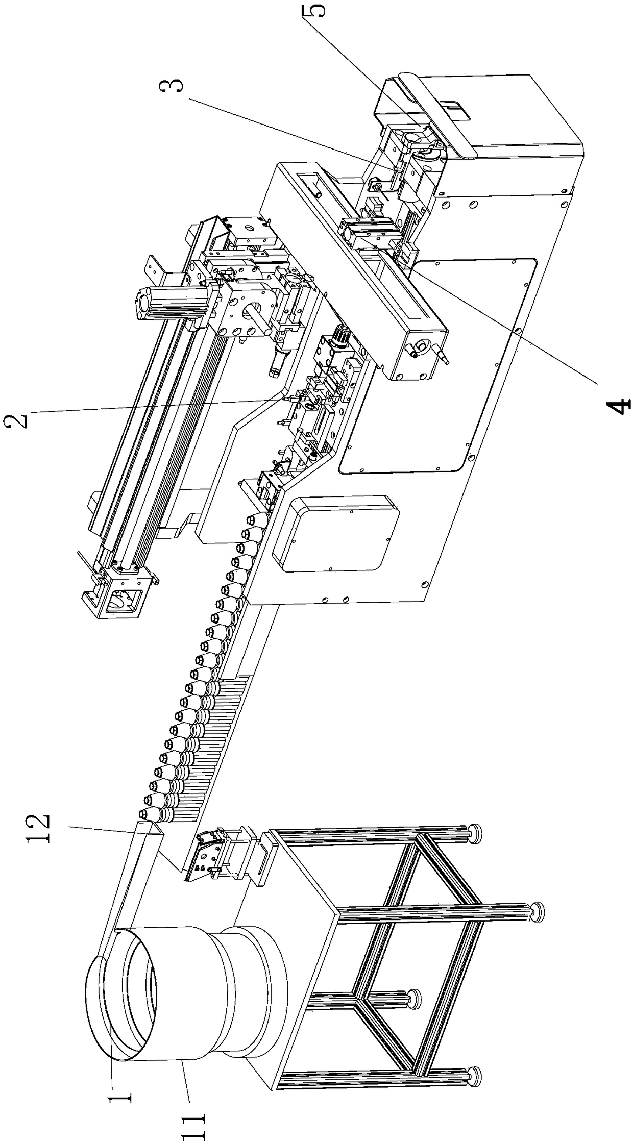
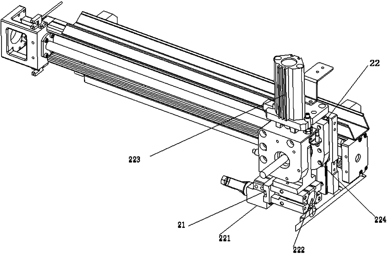
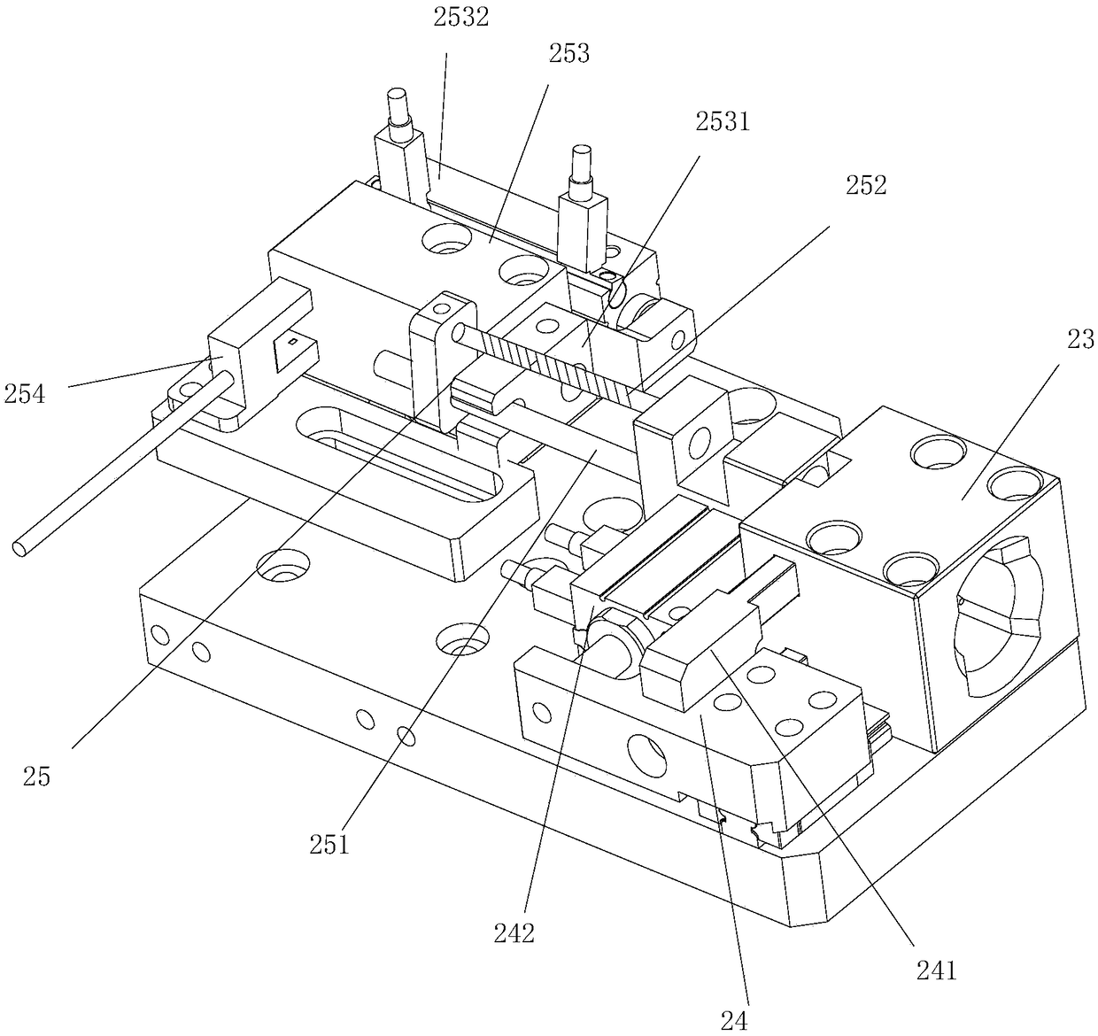
[0051] Such as figure 1 As shown, the present invention discloses an automatic nut lock machine, comprising a first feeding device 1, a second feeding device 5, a transport device 2, a locking device 3 and a feeding device 4, wherein the first feeding device Used to transport the nuts to be tightened to the first fixed station, the transport device 2 is connected to the first feeding device 1, and is used to transport the nuts at the first fixed station to the locking device 3, and the second upper The material device 5 is connected with the locking device 3, and is used to transport the cable to the locking device 3, and the locking device 3 is used to complete the tightening...


PUM


Abstract

The invention discloses an automatic nut locking machine. The automatic nut locking machine is characterized by comprising a first feeding device, a second feeding device, a conveying device, a locking device and a discharging device, wherein the first feeding device is used for completing the feeding of a nut to be tightened; the conveying device is connected with the first feeding device, and isused for conveying the fed nut to the position of the locking device; the second feeding device is connected with the locking device, and is used for conveying a cable to the position of the lockingdevice; the locking device is used for realizing the insertion of the cable into the nut and the tightening operation of the nut; and the discharging device is connected with the locking device, and is used for completing the discharging operation of the tightened nut. By adopting the technical scheme, completely automatic operation of nut locking operation is realized, and the rate of finished products is increased while the labor cost is reduced.

Description

technical field [0001] The invention relates to the technical field of mechanical equipment, in particular to a nut lock machine. Background technique [0002] The existing photovoltaic connector is to insert the terminal cable into the connector, and then use the nut to fix it. In actual production, the operation of inserting the wire and tightening the nut is mainly done manually, and the manual tightening operation is not only tightened The degree of fluctuation is relatively large, and the positioning of the cable in the nut is completely dependent on manual work, resulting in the current situation of low efficiency and high labor costs. [0003] In view of the above-mentioned defects in the existing manual tightening of nuts, the inventor actively researches and innovates on the basis of years of rich practical experience and professional knowledge in the design and manufacture of such products, and cooperates with the application of theories, in order to create an auto...

Claims


Application Information

Patent Timeline
Patent Type & Authority Patents(China)
IPC IPC(8): B23P19/06
Inventor 司向良
Owner JIANGSU BOZHIWANG AUTOMATION EQUIP CO LTD
Learn More