
Lumbar bypass minimally-invasive revealing assistant component

An auxiliary component and sideway technology, applied in the field of clinical medicine, can solve problems such as not conforming to the physiological characteristics of the operator's hand, inability to adjust, and adverse effects, etc., to achieve safe and reliable surgical procedures, increase backward tension, and improve stability Effect

Pending Publication Date: 2018-01-30
ZHEJIANG CANWELL MEDICAL DEVICES CO LTD
View PDF0 Cites 1 Cited by
  • Summary
  • Abstract
  • Description
  • Claims
  • Application Information

AI Technical Summary

Problems solved by technology

Unfortunately, although OLIF fusion devices have been released, currently OLIF surgery can only use the same retractor system as traditional lumbar surgery. The traditional surgical retractor system has the following disadvantages in the application of OLIF surgery:
[0004] 1. There is no specific fixation design, and it is difficult to meet the stability of the exposure to the surgical field when using the existing retractor to pull the soft tissue in the opposite direction;
[0005] 2. The shape of the handle of the commercial retractor is fixed, which is difficult to match the shape of the operator's hand. It often does not conform to the physiological characteristics of the operator's hand. Holding it for a long time will easily cause hand fatigue, unstable grip or even slippage, which will adversely affect the operation. ;
[0006] 3. The length of the hook cannot be stretched and adjusted, so that it cannot be adjusted reasonably according to the needs of the operator during use, which indirectly increases the difficulty of the operation and lowers the safety of the operation;
[0007] 4. Lack of light source and lighting system design, which may easily block the view and increase the difficulty of operation

Method used


Image

  • Lumbar bypass minimally-invasive revealing assistant component
  • Lumbar bypass minimally-invasive revealing assistant component
  • Lumbar bypass minimally-invasive revealing assistant component

Examples


Embodiment Construction

[0058] In order to understand the above-mentioned purpose, features and advantages of the present invention more clearly, the present invention will be further described in detail below in conjunction with the accompanying drawings and specific embodiments. It should be noted that, in the case of no conflict, the embodiments of the present application and the features in the embodiments can be combined with each other.

[0059] In the following description, many specific details are set forth in order to fully understand the present invention, but the present invention can also be implemented in other ways different from those described here, therefore, the protection scope of the present invention is not limited to the specific details disclosed below. EXAMPLE LIMITATIONS.

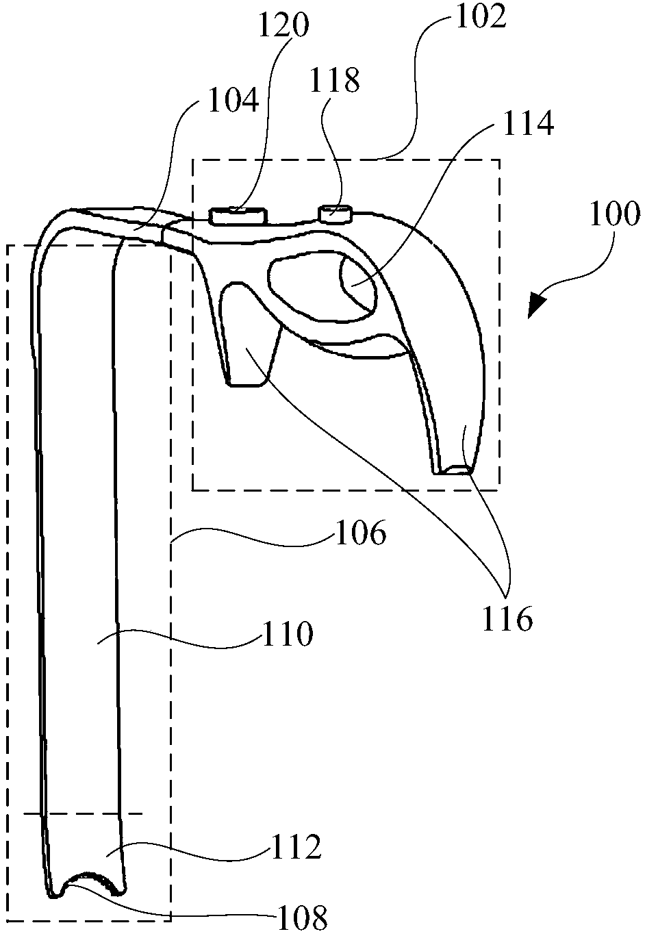
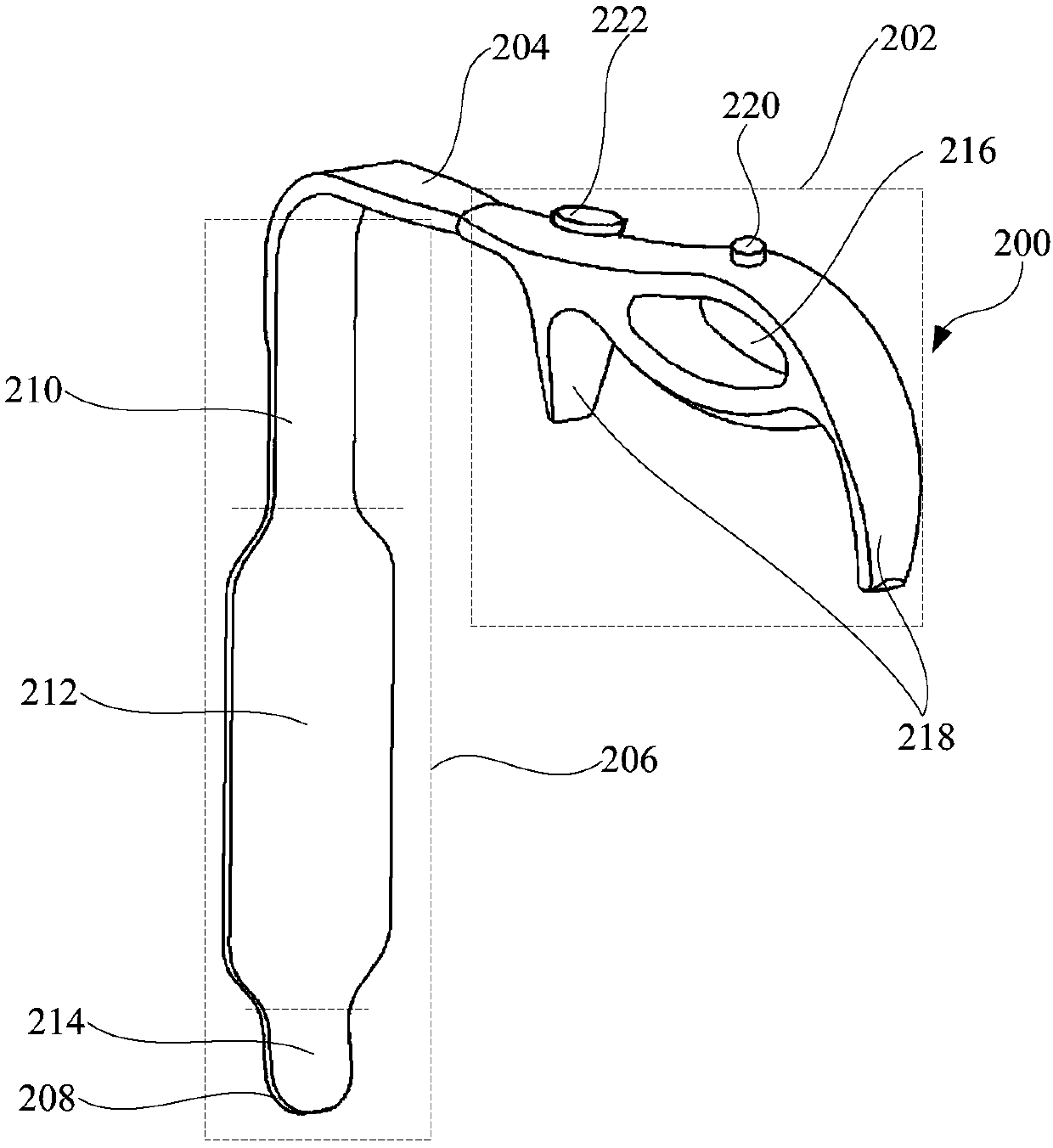
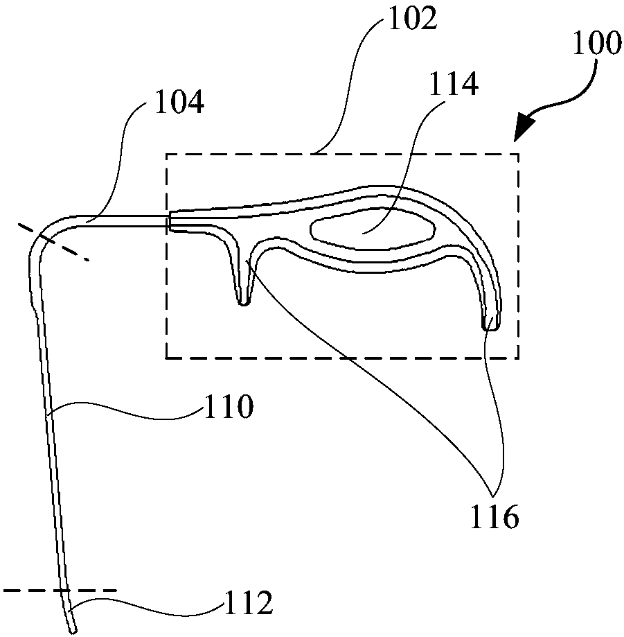
[0060] Refer below Figure 1 to Figure 9 A lumbar lateral approach minimally invasive exposure auxiliary assembly provided according to some embodiments of the present invention is described.

[0061] S...


PUM


Abstract

The invention provides a lumbar bypass minimally-invasive revealing assistant component which comprises a first drawing hook and a second drawing hook. The first drawing hook comprises a first handle,a first extensible rod and a first striping rod in sequential connection, and the end face of an open end of the first striping rod forms an arc-shaped concave face matched with an intervertebral disc; the second drawing hook comprises a second handle, a second extensible rod and a second striping rod in sequential connection, and the end face of an open end of the second striping rod forms an arc-shaped convex face. Through the technical scheme, the first drawing hook can be anchored on the intervertebral disc and has good fixing effect, so that stability of operative visual field revealingwhen drawing is performed in a direction opposite to soft tissue is improved; the second drawing hook can be free to draw tissue in an abdominal cavity and is less prone to causing damage to the softtissue, thereby being high in safety; effect of sufficiently separating and revealing operative visual field is realized by combining the first drawing hook and the second drawing hook in use.

Description

technical field [0001] The invention relates to the field of clinical medicine, in particular to a lumbar lateral minimally invasive exposure auxiliary assembly. Background technique [0002] At present, among most people in our country, low back pain is the main cause of loss of working ability. Patients with low back pain are more than 30% of the daily orthopedic outpatient visits. one of the major diseases. Since the 1980s, clinicians first applied titanium alloy fusion cages to human lumbar interbody fusion, and achieved good clinical results, because it not only meets the requirements of complete decompression, but also can perform intervertebral bone fusion and fusion. The internal fixation of the pedicle screw-rod system has therefore become the standard surgical method for the treatment of such lumbar diseases, and has also become the most common surgical method for the treatment of low back pain in addition to transforaminal surgery. However, muscle traction injur...

Claims


Application Information

Patent Timeline
Patent Type & Authority Applications(China)
IPC IPC(8): A61B17/02
Inventor 张建锋范顺武林贤丰方明彭伟许吉锋牟国良何强龙汪庆朱伟强
Owner ZHEJIANG CANWELL MEDICAL DEVICES CO LTD
Learn More