
Full-automatic cutting equipment

A fully automatic, cutting technology, applied in metal processing and other directions, which can solve the problems of missing cutting knives and cumbersome operation processes.

Active Publication Date: 2018-01-30
ZHEJIANG SHENMING SHOEMAKING MACHINERY
View PDF9 Cites 1 Cited by
  • Summary
  • Abstract
  • Description
  • Claims
  • Application Information

AI Technical Summary

Problems solved by technology

This method is not only cumbersome to operate, but the operator needs to disassemble the cutter and correct the position when replacing the cutter. At the same time, the processing site needs to provide a special knife holder for placing the cutter. The operator is easy to lose the cutter during use.

Method used


Image

  • Full-automatic cutting equipment
  • Full-automatic cutting equipment
  • Full-automatic cutting equipment

Examples


Embodiment Construction

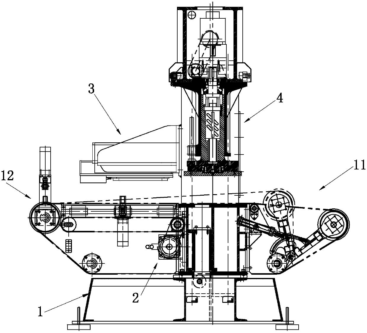
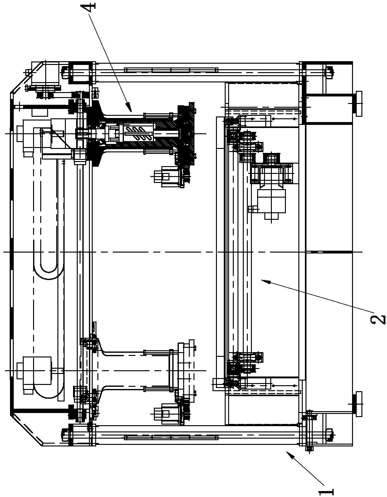
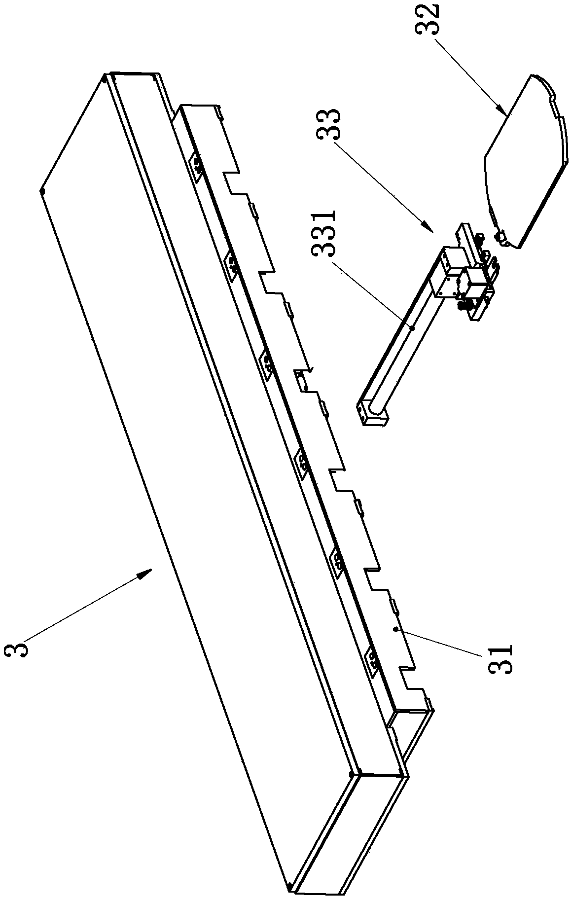
[0030] like figure 1 — Figure 9 A full-automatic cutting device shown includes a body 1, a feed end 11 and a discharge end 12 arranged on the body 1, and a cutting device for cutting is provided between the feed end and the 11 discharge end 12 And the conveying device 2 that will output the material that has been cut to the discharge end 12, the cutting device includes a cutter assembly 3 and a cutting assembly 4, and the cutter assembly 3 includes a knife seat 31 fixed on the body 1, a set A number of die mounting plates 32 for the cutting knife to be installed in the knife seat 31 and a number of groups corresponding to the number of die mounting plates 32 that can be taken out from the knife seat 31 or placed in the knife seat 31 Extraction mechanism 33; Cutting assembly 4 comprises the support 41 that organic body 1 is fixed, the driving source 42 erected on the support 41, the lifting seat 43 linked with the driving source 42 and is connected with the lifting seat 43 an...


PUM


Abstract

The invention relates to material cutting-off machinery, in particular to full-automatic cutting equipment. According to the technical scheme, the full-automatic cutting equipment comprises a body, afeeding end and a discharging end, wherein the feeding end and the discharging end are arranged on the body; a cutting device for cutting off materials and a conveying device for conveying the cut materials to the discharging end are arranged between the feeding end and the discharging end; the cutting device comprises a cutter assembly and a cutting assembly; the cutter assembly comprises a cutter seat, cutting die mounting plates and a plurality of lifting and taking mechanisms; the cutter seat is fixedly arranged on the body; the cutting die mounting plates are arranged in the cutter seat;cutters are mounted on the cutting die mounting plates; the lifting and taking mechanisms can take out the cutting die mounting plates from the inside of the cutter seat or placing the cutting die mounting plates into the cutter seat; and the number of the lifting and taking mechanisms corresponds to that of the cutting die mounting plates. By the technical scheme, the full-automatic cutting equipment facilitates mounting or changing of a conveying belt, is provided with the cutter seat, can lift and take the cutters as needed, has the improved cutting efficiency, and is stable in punching andhigh in precision.

Description

technical field [0001] The invention relates to a material cutting machine, in particular to a fully automatic cutting device. Background technique [0002] Cutting machine is a kind of special equipment used in industry to shape and cut leather, plastic, canvas, nylon and other materials to make them conform to the blanking size of processed products. [0003] The traditional cutting machine is mainly composed of a body, a feed end and a discharge end arranged on the body. There is a cutting device for cutting between the feed end and the discharge end, and a conveyor for outputting the cut material to the discharge end. device. [0004] The conveying device is usually composed of several rotatable rollers erected on the machine body and a conveyor belt wound on the rollers. Since the axial direction of the roller is fixed to the machine body during installation, the conveyor belt needs to be installed around the roller after the strip-shaped conveyor belt body is install...

Claims


Application Information

Patent Timeline
Patent Type & Authority Applications(China)
IPC IPC(8): B26D1/08B26D7/26B26D7/06
Inventor 吴新华
Owner ZHEJIANG SHENMING SHOEMAKING MACHINERY
Learn More