
Automatic profile observing apparatus driven by ocean wave energy

A technology for profile observation and wave energy, applied in the field of automatic profile observation devices driven by ocean wave energy, can solve the problems of technical confidentiality, complex structure of Wirewalker, high cost, improve data acquisition efficiency, reduce instrument use cost, volume and weight reduced effect

Pending Publication Date: 2018-01-30
SECOND INST OF OCEANOGRAPHY MNR
View PDF11 Cites 24 Cited by
  • Summary
  • Abstract
  • Description
  • Claims
  • Application Information

AI Technical Summary

Problems solved by technology

This method requires a motor drive, which consumes a lot of energy and costs a lot
2. The buoyancy of the overall platform changes to make the sensor rise or sink
However, Seahorse is triggered by an electric switch when it floats up, which requires a motor, battery and control system. The structure of Wirewalker is complicated, and the technology is kept secret, so the cost of introduction remains high.
[0004] my country's ocean buoys, submersible buoys and other automatic observation platform technologies have developed rapidly, but there have been no reports of automatic profile observation devices using wave energy. With the increase in marine scientific research and military needs, there is an urgent need for a simple operation, easy maintenance, and low cost. , an automatic profile observation device suitable for a wide range of sea areas

Method used


Image

  • Automatic profile observing apparatus driven by ocean wave energy
  • Automatic profile observing apparatus driven by ocean wave energy
  • Automatic profile observing apparatus driven by ocean wave energy

Examples


Embodiment Construction

[0026] The specific implementation manner of the present invention will be described in detail below in conjunction with the accompanying drawings.

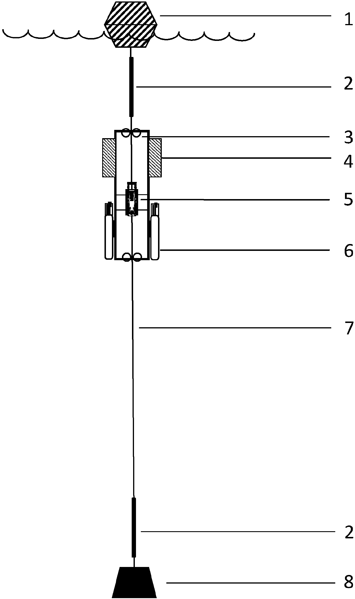
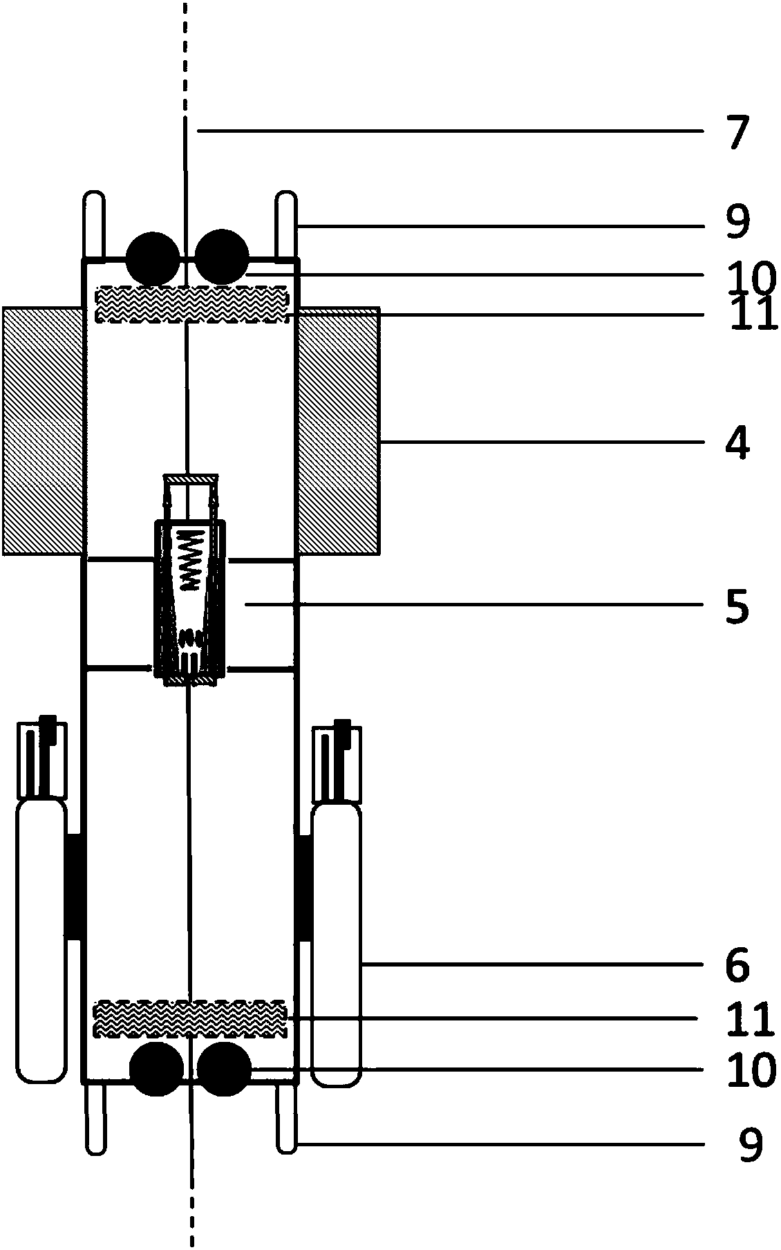
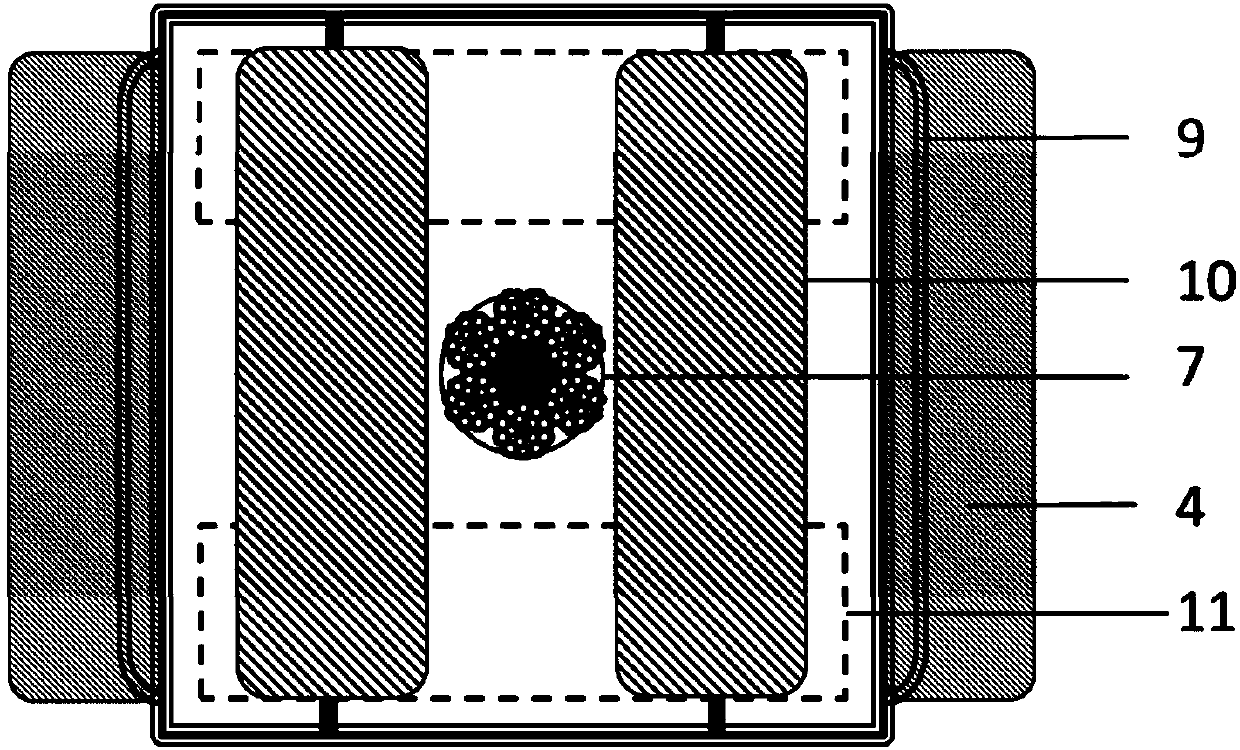
[0027] Such as Figure 1 to Figure 7 As shown, the present invention provides a specific embodiment of an automatic profile observation device driven by ocean wave energy.

[0028] Such as figure 1 Shown: the mooring system floating ball 1 is located on the sea surface, so that the whole mooring system floats on the upper layer of the sea surface. The bottom connects the steel cable 7, and the end connects the anchorage weight 8 to keep the anchorage vertical. The instrument bench 3 is passed through by the steel cable 7, and can move up and down along the steel cable 7, and the moving distance is limited by the bench stopper 2.

[0029] Such as figure 2 As shown: the instrument stand 3 includes a buoyancy material 4, a stand handle 9, a cylindrical bearing 10, a block 11, etc.; it is a cuboid hollow structure with a length,...


PUM


Abstract

The invention discloses an automatic profile observing apparatus driven by ocean wave energy. The automatic profile observing apparatus comprises a mooring floating ball, a steel cable, a mooring weight, an instrument rack, an upper rack limiting device and a lower rack limiting device; the instrument rack is penetrated by a steel cable and positioned between the two rack limiting devices, the instrument rack has net buoyance, a single-direction moving module is fixedly installed on a middle-upper position inside the instrument rack, in the upward and downward moving processes of waves, the instrument rack has an underwater net displacement, the waves continuously vibrate, the instrument rack moves towards deep water along the steel cable and finally collides with the lower rack limiting device to float upwards. After the instrument rack floats upwards to the upper rack limiting device and is assembled, the instrument rack can move to the deep water under the effect of the waves. By virtue of full mechanical design, the automatic profile observing apparatus has no electric power consumption; compared with the existing commercial automatic profile platform, the size and the weight are greatly reduced; a set of sensors can be carried to perform the full-profile observation and to acquire real-time continuous high-resolution data, so that the application cost of the instrument isreduced, and the data acquisition efficiency is increased.

Description

technical field [0001] The invention belongs to the technical field of seawater automatic observation, and is applicable to a carrying platform designed for automatic section observation by integrating various sensors in the ocean, and in particular relates to an automatic section observation device driven by ocean wave energy. Background technique [0002] Today's ocean observations, forecasts, and research rely more and more on automatic and continuous observations of various physical, ecological, and chemical parameters, such as the velocity of ocean currents, the observation and forecast of El Nino phenomena, and the transfer of nutrients in estuaries, etc., to obtain high time and space. Resolution data is the key and foundation. The classic observation methods that are often used at present are generally various mooring systems integrating multiple sensors, including buoys, submersible buoys, bottom platforms, landers and other carrying platforms. The sensor is fixed ...

Claims


Application Information

Patent Timeline
Patent Type & Authority Applications(China)
IPC IPC(8): G01N33/18B63B22/00
CPCY02E10/30
Inventor 王奎陈建芳
Owner SECOND INST OF OCEANOGRAPHY MNR
Learn More