
Electric vehicle thermal management control method and system

A thermal management, electric vehicle technology, applied in electric vehicles, battery/fuel cell control devices, circuits, etc., can solve the problems of unintelligent control, reduced passenger driving experience, loud noise, etc., to improve energy saving efficiency and avoid adjustment difficulties or can not adjust, reduce the effect of energy waste

Active Publication Date: 2019-07-19
深圳福源特新能源有限公司
View PDF6 Cites 0 Cited by
  • Summary
  • Abstract
  • Description
  • Claims
  • Application Information

AI Technical Summary

Problems solved by technology

[0002] In the existing electric vehicle thermal management control method, the control of the cooling equipment mainly adopts the three-stage control method. When the temperature of the battery core reaches a, the first gear speed is used; when the battery temperature reaches b, the second gear speed is used; When the temperature of the battery core reaches c, use the 3rd gear speed to control the temperature of the battery core; but this control is not intelligent, resulting in waste of electric energy, high noise, and poor driving experience for passengers

Method used


Image

  • Electric vehicle thermal management control method and system
  • Electric vehicle thermal management control method and system
  • Electric vehicle thermal management control method and system

Examples


Embodiment Construction

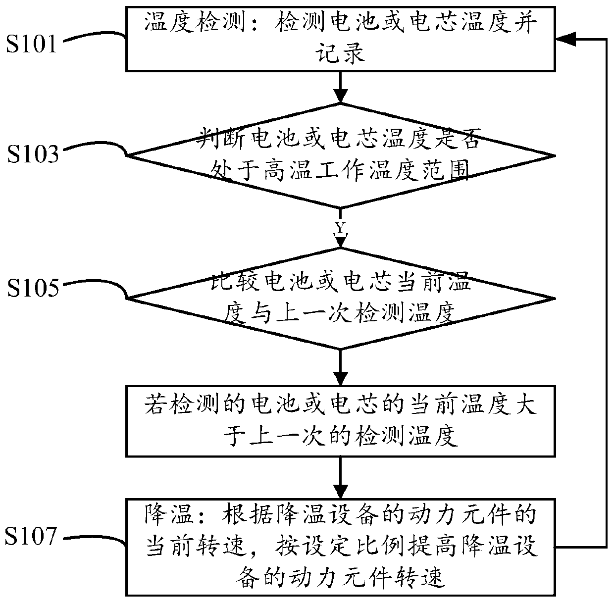
[0070] like figure 1 As shown, a thermal management method for an electric vehicle according to an embodiment of the present invention includes the following steps:

[0071] Step S101, temperature detection: the temperature of the battery or cell is detected and recorded,

[0072] Step S103, temperature judgment: judging whether the temperature of the battery or cell is within the high temperature working temperature range,

[0073] If the high temperature operating temperature range is not exceeded, execute

[0074] Step S105, temperature comparison: compare the current temperature with the previous temperature,

[0075] If the current temperature is greater than the previous temperature, execute

[0076] Step S107, cooling: according to the set ratio, proportionally increase the rotational speed of the power element of the cooling device;

[0077] Repeat the above steps until the power element of the cooling device is running at full speed.

[0078] The cooling device i...


PUM


Abstract

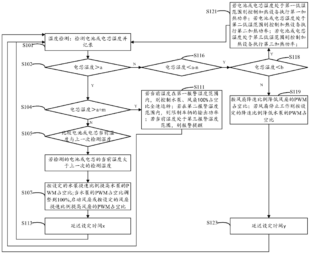
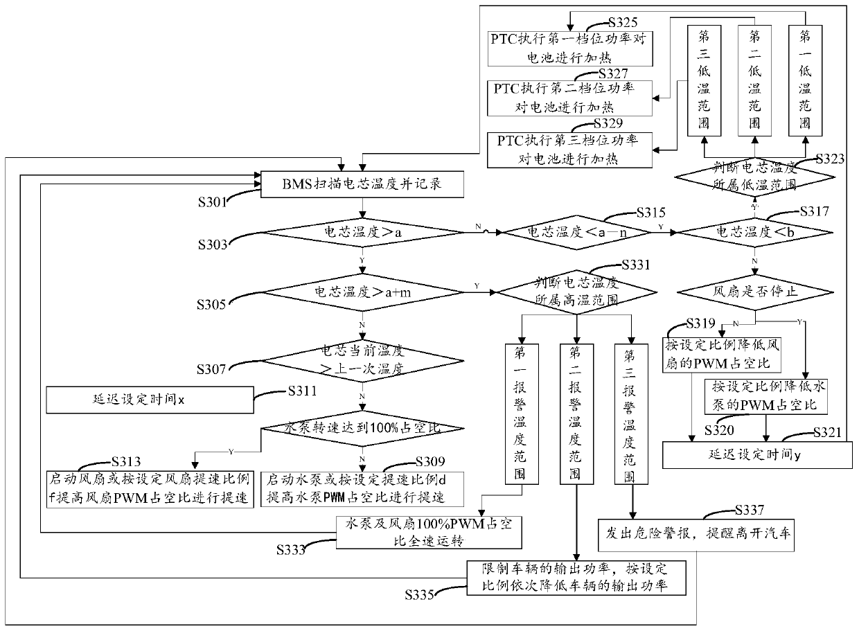
The invention discloses an electric vehicle heat management control method and an electric vehicle heat management control system. The electric vehicle heat management control method comprises the following steps: performing temperature detection, namely detecting and recording the temperature of a battery or a battery core; performing temperature judgment, namely judging whether the temperature of the battery or the battery core is within a high-temperature working temperature range; if the temperature of the battery or the battery core is within the high-temperature working temperature range, executing temperature comparison; performing temperature comparison, namely comparing the current temperature with the last temperature; if the current temperature is higher than the last temperature, executing a cooling operation; cooling, namely proportionally increasing the rotation speed of a power component of cooling equipment; repeating the former step until the power component of the cooling equipment is in full-speed operation. According to the electric vehicle heat management control method and the electric vehicle heat management control system, through setting of an adjusting proportion, the rotation speed of the power component of the cooling equipment is increased according to the set proportion, and the adjusting proportion can be revised to the optimal adjusting proportion according to an actual situation, an optimal operating state of the whole equipment is met and the energy consumption is lowered; the before and after temperatures of the battery core are compared,the power of the cooling equipment is timely adjusted for cooling, the battery is adjusted to the optimal working temperature range in the most energy-saving way, and the energy consumption is loweredwhile the working efficiency of the battery is improved.

Description

technical field [0001] The invention relates to the field of electric vehicles, in particular to a thermal management method and system for an electric vehicle. Background technique [0002] In the existing electric vehicle thermal management control method, the control of the cooling equipment mainly adopts the three-stage time control method. When the cell temperature reaches a, the first gear speed is used; when the cell temperature reaches b, the second gear speed is used; When the cell temperature reaches c, the 3rd gear speed is used to control the cell temperature; however, this control is not intelligent, resulting in waste of electric energy, loud noise, and reduced driving experience for passengers. [0003] If it is assumed that the maximum working temperature of the battery cell needs to be controlled below 40C, when the speed of the water pump / fan is used to block a, the temperature of the battery cell is 42C, which still exceeds the standard 40C. Therefore, it ...

Claims


Application Information

Patent Timeline
Patent Type & Authority Patents(China)
IPC IPC(8): H01M10/48H01M10/635H01M10/637B60L58/26
CPCY02E60/10Y02T10/70
Inventor 汤贤袖
Owner 深圳福源特新能源有限公司
Learn More