
Near-field active mirror image focusing antenna

A technology of focusing antenna and source mirror, applied to antennas, antenna arrays that are powered on separately, electrical components, etc., can solve the problems of unable to form multi-focal spots, complex circuit structure, unable to form focal spots, etc., to achieve excellent focusing effect and focus More effect, lower lobe effect

Pending Publication Date: 2018-01-30
成都瑞德星无线技术有限公司
View PDF11 Cites 6 Cited by
  • Summary
  • Abstract
  • Description
  • Claims
  • Application Information

AI Technical Summary

Problems solved by technology

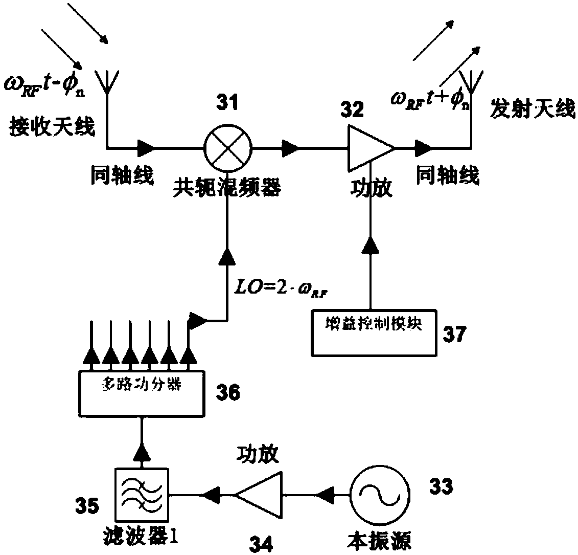
However, the phase conjugate circuit of the lens needs to be frequency-converted twice, and the phase-locking technology is adopted at the same time, so the whole circuit structure is relatively complicated.
At the same time, due to the use of phase-locking technology, the signal amplitude of each output is the same, so the amplitude cannot be adjusted
In addition, the phase-locked loop can only lock one signal, so the lens cannot form a multi-focus spot
Moreover, the lens is only composed of a one-dimensional line array, so it cannot form a focal spot, but can only form a cylinder with relatively concentrated energy at a fixed position.

Method used


Image

  • Near-field active mirror image focusing antenna
  • Near-field active mirror image focusing antenna
  • Near-field active mirror image focusing antenna

Examples


Embodiment Construction

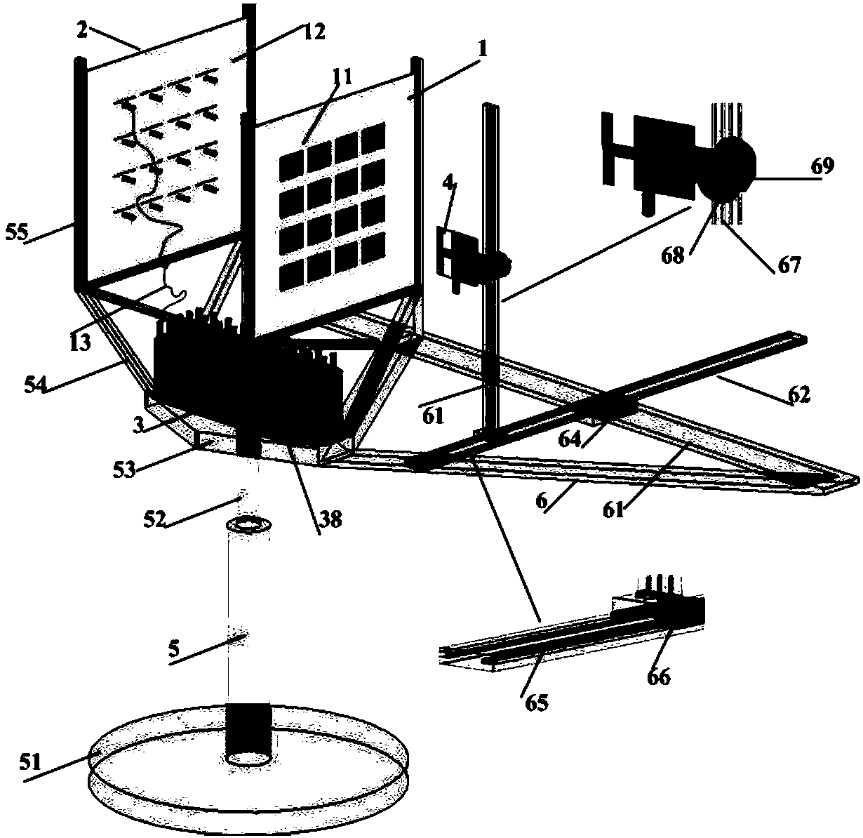
[0019]The present invention will be further described below in conjunction with the accompanying drawings and specific embodiments: a near-field active image focusing antenna, including a receiving antenna array 1, a transmitting antenna array 2, a phase conjugate circuit module 3, an illumination antenna 4, a base 5 and an illumination Antenna mobile station 6; described transmitting antenna array 1 and receiving antenna array 2 are exactly the same and placed on the base 5 back to back, and the placement distance can be any value; the array elements 11 of transmitting antenna array 1 and receiving antenna array 2 can be arbitrary In the form of unidirectional antenna, there is a floor on the back of the array element 11, and there are coaxial connectors 12 on the floor. The distance between the array elements 11 can be arbitrarily selected. Here we choose a slotted patch antenna with a working frequency of 2.45GHz as the array element 11. The transceiver antenna array is a 4x...


PUM


Abstract

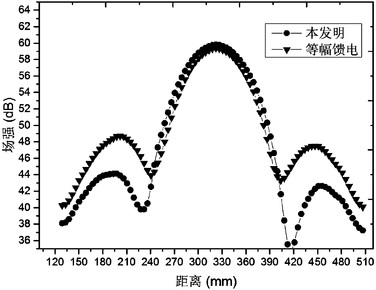
The invention discloses a near-field active mirror image focusing antenna, which comprises a receiving antenna array, a transmitting antenna array, a phase conjugate circuit module, an illuminating antenna, a base and an illuminating antenna mobile station. The near-field active mirror image focusing antenna can be used for microwave hyperthermia, microwave detection and microwave energy transmission. The near-field active mirror image focusing antenna has the advantages that a focal position is controllable, multiple focuses can be formed, low side-lobe amplitude distribution is formed on a transmitting aperture surface in a self-adaptive manner, and the focusing effect is excellent.

Description

technical field [0001] The invention belongs to the field of microwave and millimeter wave systems, in particular to a near-field active image focusing antenna. Background technique [0002] Focusing antennas have the ability to focus electromagnetic energy in a certain space range. Because they can concentrate a large amount of energy in a very small space range, they are widely used in microwave hyperthermia, microwave energy transmission, near-field communication, and microwave detection. [0003] Traditional focusing antennas are mainly based on passive arrays, which are divided into planar focusing antennas and non-planar focusing antennas. Most planar focusing antennas use metal patches as array elements. By controlling the phase of the radiation field of the metal patch, the phase of the entire aperture surface satisfies the spherical distribution, and the near-field electromagnetic energy is focused. Non-planar focusing antennas mostly use dielectric lenses, parabol...

Claims


Application Information

Patent Timeline
Patent Type & Authority Applications(China)
IPC IPC(8): H01Q21/06H01Q3/02
Inventor 林先其杨永穆刘士林常慧萍黄登祥李立江张廷钎袁图友
Owner 成都瑞德星无线技术有限公司
Learn More