Four-dimensional antenna array based on single-pole multi-throw switch

A single-pole multi-throw switch and antenna array technology, applied in the field of four-dimensional antenna arrays, can solve the problems of sharp changes in transient directivity coefficients, low array antenna gain, narrow bandwidth, etc., to reduce computational complexity, improve gain, and optimize variables. reduced effect

Active Publication Date: 2012-08-22
UNIV OF ELECTRONICS SCI & TECH OF CHINA
View PDF4 Cites 56 Cited by
  • Summary
  • Abstract
  • Description
  • Claims
  • Application Information

AI Technical Summary

Problems solved by technology

[0005] In view of the above technical background, the present invention proposes a four-dimensional antenna array structure design based on single-pole multi-throw switches, the purpose of which

Method used


Image

  • Four-dimensional antenna array based on single-pole multi-throw switch
  • Four-dimensional antenna array based on single-pole multi-throw switch
  • Four-dimensional antenna array based on single-pole multi-throw switch

Examples


Embodiment 1

[0022] Embodiment 1: Structural design of 16-unit low-sidelobe four-dimensional antenna array based on single-pole double-throw switches

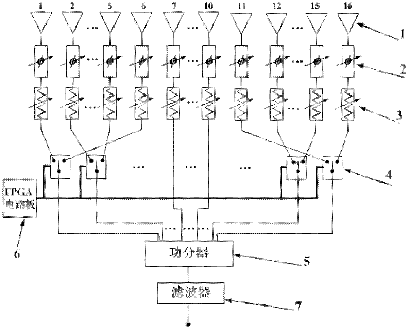
[0023] refer to figure 1 , In this embodiment, a four-dimensional antenna array composed of 16 omnidirectional array elements is used. The array antenna mainly includes an antenna unit (1), a phase shifter (2), a variable amplitude attenuator (3), a single-pole double-throw switch (4), a power splitter (5), an FPGA circuit board (6) and filter (7). In the symmetrical array structure, the antenna elements are equally spaced at half wavelengths. The 6 units on the left and right sides (No. 1-6 and 11-16) are controlled by the SPDT switch, and the four units in the middle (No. 7-10) are not connected to the switch. All switches are controlled by the FPGA board.

[0024] Different from the traditional four-dimensional antenna array, this patent adopts a single-pole double-throw switch to control two antenna unit channels at the same time. F...

Embodiment 2

[0027]Embodiment 2: An 8-unit multi-beam four-dimensional antenna array structure device based on a single-pole eight-throw switch

[0028] refer to Image 6 In this embodiment, a four-dimensional antenna array composed of 8 omnidirectional array units is adopted, and the array antenna structure is composed of 8 antenna units (1), FPGA circuit board (6), filter (7) and single-pole eight-throw switch (8) Composition. The single-pole eight-throw switch conducts 8 units sequentially, and each unit conducts for 0.125 periods in one modulation cycle. Figure 7 is the control sequence of each unit, where the black shaded part indicates that the switch is in the on state. Figure 8 It is the direction diagram obtained by numerical simulation, including the direction diagram of the center frequency and three positive and negative sidebands. Depend on Figure 8 It can be seen that the signals of different sidebands point to different angles respectively, and their peak levels diffe...


PUM


Abstract

The invention discloses a four-dimensional antenna array based on a single-pole multi-throw switch. The basic structure of the four-dimensional antenna array comprises an antenna unit, a phase shifter, a variable amplitude fader, the single-pole multi-throw radio-frequency switch, a power divider, an FPGA (Field Programmable Gate Array) circuit board and a filter. The greatest innovation of the invention is that the single-pole multi-throw switch replaces a single-pole single-throw switch in a traditional four-dimensional antenna array. Compared with the original four-dimensional antenna array based on the single-pole single-throw switch, a small amount of radio-frequency switches are only used in the structural design proposed provided by the invention; and in the combination of low side lobes or multi-beam directional diagrams, the gain of an antenna is greatly improved, the transient directivity factor of the antenna and the stability of the gain in the modulation period are not changed. The dimension of the antenna is changed reasonably, so as to constitute other specific embodiments of the invention. The four-dimensional antenna array is used for wireless communication and is also used in a radar system.

Description

technical field [0001] The invention belongs to the technical field of antenna engineering and relates to a novel array antenna, specifically a four-dimensional antenna array based on a single-pole multi-throw switch. Background technique [0002] When traditional phased array antennas synthesize low / ultra-low sidelobe patterns, the dynamic range ratio of the excitation amplitude is often very high, which leads to excessively high requirements on the accuracy of the feed network, and sometimes it cannot even be realized in practice. The four-dimensional antenna array formed by introducing the time variable into the conventional antenna array with three-dimensional spatial changes can realize the amplitude and phase weighting of the spatial array elements through time weighting, thereby increasing the degree of freedom in the design of the antenna array, making the four-dimensional antenna Compared with conventional antenna arrays, antenna arrays have more design advantages, ...

Claims


Application Information

Patent Timeline
IPC IPC(8): H01Q21/00H01Q23/00H01Q3/26
Inventor 杨仕文朱全江姚瑞林李冰黄明聂在平
Owner UNIV OF ELECTRONICS SCI & TECH OF CHINA
Why Eureka
Try Eureka