Dust removal device for communication machine room

A technology of dust removal device and communication room, applied in particle charging/ionization places, electrode structure, electrostatic separation, etc., can solve problems such as inability to effectively filter dust, unsatisfactory dust removal effect, damage to health, etc. Better effect, safe and practical effect

Inactive Publication Date: 2018-02-02
江门市中讯通信技术有限公司
View PDF1 Cites 1 Cited by
  • Summary
  • Abstract
  • Description
  • Claims
  • Application Information

AI Technical Summary

Problems solved by technology

[0003] Existing communication equipment rooms usually use exhaust devices to ventilate the air in the equipment room, which has the effect of heat dissipation and cooling, but it cannot effectively filter the dust in the air, because dust is easy to accumulate on communication equipment and affects heat dissipation; some existing electrostatic dust removal equipment can It is used in the communication room, but due to the connection of high-voltage power supply, it is easy to cause static electricity accumulation, which has potential safety hazards, especially the ozone generated by high-voltage discharge will damage health, accelerate the aging of components, and the dust removal effect is not ideal, so there is an urgent need for a dust removal device suitable for communication rooms

Method used


Image

  • Dust removal device for communication machine room
  • Dust removal device for communication machine room
  • Dust removal device for communication machine room

Examples


Embodiment Construction

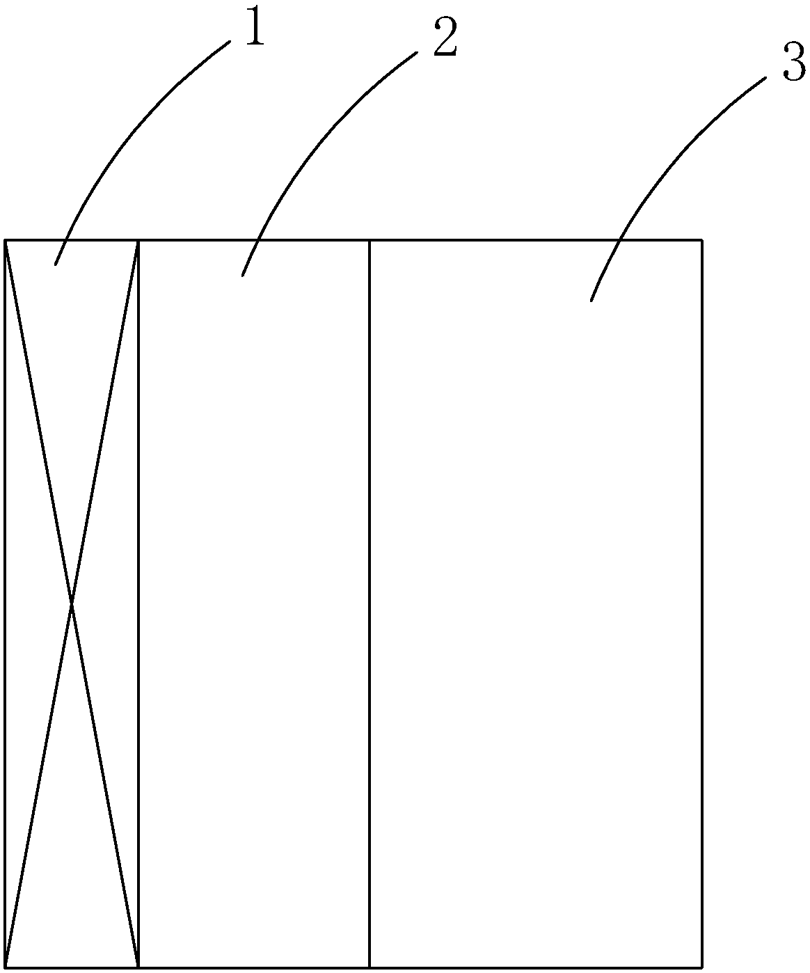
[0018] refer to figure 1 and 2 , a dust removal device for a communication machine room of the present invention, comprising a housing, an air inlet and an air outlet are arranged in the housing, and an exhaust fan 1, a polarization device 2 and an electrostatic dust removal device 3 are arranged in sequence from the air inlet to the air outlet, Wherein the polarizing device 2 comprises a negative high-voltage particle generator, a charged grounding plate and a charged electrode plate, on which a plurality of through holes for air to pass through are provided on the charged electrode plate, and a plurality of charged electrodes corresponding to the through holes are arranged, According to the principle of tip discharge, the tip of the charged electrode will emit a large number of electrons outward. When the air to be purified passes through the polarizing device 2, the solid particles in the air will be negatively charged and converted into negatively charged particles. Dust ...


PUM


Abstract

The invention discloses a dust removal device for a communication machine room. The dust removal device comprises a shell. An air inlet and an air outlet are formed in the shell. An exhaust fan, a polarization device and an electrostatic precipitator are sequentially arranged from the air inlet to the air outlet. The electrostatic precipitator comprises a frame, a positive pole plate and a negative pole plate, wherein the positive pole plate and the negative pole plate are arranged on the inner side of the frame. The positive pole plate and the negative pole plate are spaced, and a passage isreserved between the adjacent pole plates. The passage is a bent passage. The surface of the positive pole plate and the surface of the negative pole plate are coated with insulating layers. Dust removal is performed by the adoption of the electrostatic precipitator, when the electrostatic precipitator operates, gas containing dust is electrically separated when passing through a high-voltage electrostatic field in work, the dust is adsorbed to the pole plates, and the dust removal effect is achieved; the air filtering path can be extended due to the bent passage, and the dust removal effect is better; furthermore, through covering of the insulating layers, no discharging phenomenon is generated between the positive pole plate and the negative pole plate, and therefore ozone generation isavoided; and the structure is safe, practical, stable and reliable.

Description

technical field [0001] The invention relates to a dust removal device, in particular to a dust removal device suitable for a communication machine room. Background technique [0002] Electrostatic dust collection is a kind of gas dust removal method. The dust-containing gas is electrically separated when it passes through a high-voltage electrostatic field. After the dust particles and negative ions are combined with negative charges, they tend to discharge and deposit on the surface of the anode. A dust collection method that uses an electrostatic field to ionize the gas so that the dust particles are charged and adsorbed to the electrode. In the past, it was often used in coal-fueled factories and power stations to collect coal ash and dust in the flue gas. Now there are dust removal and sterilization products that can be used in households. [0003] Existing communication equipment rooms usually use exhaust devices to ventilate the air in the equipment room, which has th...

Claims


Application Information

Patent Timeline
Patent Type & Authority Applications(China)
IPC IPC(8): B03C3/34B03C3/38B03C3/41B03C3/45
CPCB03C3/34B03C3/38B03C3/41B03C3/45
Inventor 彭锡基
Owner 江门市中讯通信技术有限公司
Why Eureka
Try Eureka