
Horizontal rotary-mold extrusion forming device for improving performance of products

A technology of extrusion forming and horizontal extruding machine, which is applied in the field of horizontal rotary die extrusion forming device, can solve the problems that the mechanical properties of extruded products cannot meet the requirements and other problems, achieve reduction of axial deformation stress and reduce forming load, the effect of improving mechanical properties

Inactive Publication Date: 2018-02-02
HARBIN INST OF TECH
View PDF4 Cites 9 Cited by
  • Summary
  • Abstract
  • Description
  • Claims
  • Application Information

AI Technical Summary

Problems solved by technology

[0007] The purpose of this invention is to solve the problem that the mechanical properties of extruded products cannot meet the requirements when extruding and preparing products such as rods and pipes on traditional horizontal extruders, and to provide a horizontal rotary die for improving product performance Extrusion device

Method used


Image

  • Horizontal rotary-mold extrusion forming device for improving performance of products
  • Horizontal rotary-mold extrusion forming device for improving performance of products
  • Horizontal rotary-mold extrusion forming device for improving performance of products

Examples


specific Embodiment approach 1

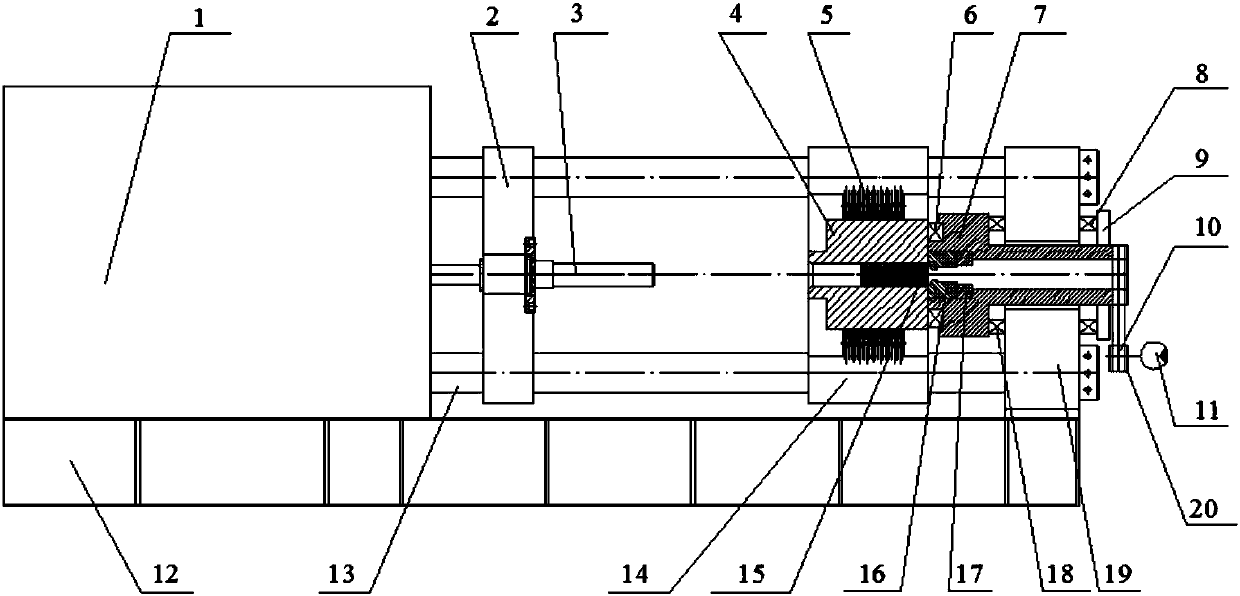
[0027] Specific Embodiment 1: This embodiment is a horizontal rotary die extrusion forming device for improving product performance, which includes a horizontal extruder 1 and a rotary die device 20, and the rotary die device 20 is arranged on the front beam 19 On, the rotary mold device 20 is composed of a servo motor 11, a transmission mechanism 10, a rotary mold cover 7, a mold 16, a mold base 17, a first thrust bearing 6, a second thrust bearing 8, a third thrust bearing 18 and a locking The end cover 9 is composed of the horizontal extruder 1, the movable platform 2, the extrusion cylinder support 14, the front beam 19 and the four expansion columns 13, which are horizontally installed on the upper surface of the frame 12; the movable platform 2 1. Extrusion barrel support 14 and front crossbeam 19 are arranged side by side successively along the length direction of frame 12, and described extrusion barrel support 14 is positioned between movable platform 2 and front cross...

specific Embodiment approach 2

[0029] Embodiment 2: This embodiment is different from Embodiment 1 in that the movable platform 2 slides on four tension columns 13 . Others are the same as in the first embodiment.

specific Embodiment approach 3

[0030] Embodiment 3: This embodiment differs from Embodiment 1 or Embodiment 2 in that the transmission mechanism 10 is gear transmission or sprocket transmission. Others are the same as those in the first or second embodiment.


PUM

PropertyMeasurementUnit
Average grain sizeaaaaaaaaaa
Tensile strengthaaaaaaaaaa
Average grain sizeaaaaaaaaaa

Abstract

The invention provides a horizontal rotary-mold extrusion forming device for improving performance of products, relates to the horizontal rotary-mold extrusion forming device for improving performanceof extruded sections, and belongs to the technical field of metal plastic-forming techniques. The horizontal rotary-mold extrusion forming device comprises a horizontal extruding machine and a rotarymold device, wherein the rotary mold device is arranged on a front cross beam and composed of a servo motor, a transmission mechanism, a rotary mold sleeve, a mold, a mold seat, a first thrust bearing, a second thrust bearing, a third thrust bearing and a locking end cover. The horizontal extruding machine, a movable platform, an extruding barrel support, the front cross beam and four extension columns are horizontally mounted on the upper surface of a machine frame. The movable platform, the extruding barrel support and the front cross beam are sequentially arranged side by side in the length direction of the machine frame, and the extruding barrel support is located between the movable platform and the front cross beam. The rotary mold device is adopted in the extruding process, throughthe rotation effect of the mold, severe shear deformation is generated in a deformation area when a product is formed by extrusion, high plastic deformation can be obtained, and thus grains are refined.

Description

technical field [0001] The invention relates to a horizontal rotary die extrusion forming device for improving the performance of extruded profiles, and belongs to the technical field of metal plastic forming technology. Background technique [0002] Extrusion is a relatively common forming method in plastic forming, and it is the main forming process for preparing rods and pipes in the field of metal plastic processing. For some lightweight materials such as aluminum alloys and magnesium alloys, their original mechanical properties are not ideal, and their mechanical properties can be improved after certain plastic forming. Extrusion process is a main plastic forming method to improve its mechanical properties while obtaining extruded products such as metal rods and pipes. With the lightweight development requirements of aviation, aerospace and weaponry, higher requirements are placed on the performance indicators of lightweight materials such as aluminum alloys and magnes...

Claims


Application Information

Patent Timeline
IPC IPC(8): B21C23/08B21C23/00B21C29/00
CPCB21C23/08B21C23/001B21C29/003
Inventor 滕步刚李丙
Owner HARBIN INST OF TECH
Learn More