Wood bending machine
A wood bending machine and frame technology, applied in the field of wood bending equipment, can solve the problems of insufficient force at both ends of wood, failure of bending forming, waste of wood, etc., and achieve the effect of high precision of wood forming effect and good effect of bending forming
- Summary
- Abstract
- Description
- Claims
- Application Information
AI Technical Summary
Problems solved by technology
Method used
Image
Examples
Embodiment 1
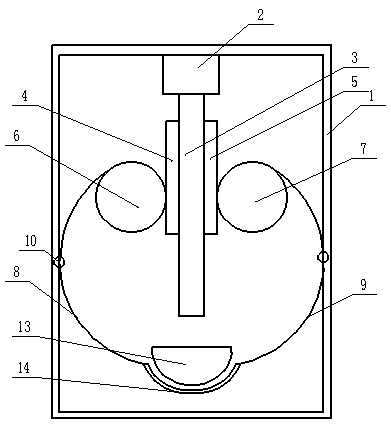
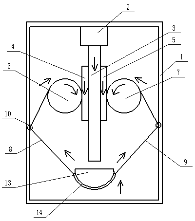
[0027] Such as figure 1 As shown, a wood bending machine, the frame 1 is a rectangular frame, the lower part of the rectangular frame is placed with a mold 13, the mold 13 is clamped with the rectangular frame, the lower surface of the mold 13 is a curved surface, and the mold 13 is connected to the bottom of the frame 1 Channels of curved wood 14 are formed therebetween. A hydraulic cylinder 2 is installed at the frame top of the rectangular frame, the cylinder body of the hydraulic cylinder 2 is connected with the rectangular frame by bolts, and the output shaft 3 of the hydraulic cylinder is vertically downward.
[0028] The left side of the hydraulic cylinder output shaft 3 is welded with a vertical first rack 4, and a first gear 6 is also installed on the same side. The first gear 6 is rotatably connected to the frame 1. The first gear 6 and the first rack 4 meshing, the first gear 6 side is coaxially equipped with a winding reel one, the winding reel one is splined with...
Embodiment 2
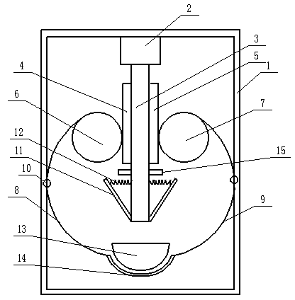
[0032] The difference between embodiment 2 and embodiment 1 is only that: embodiment 2 adds a steam box 15 and a wing plate 11, and a number of through holes are evenly distributed in the longitudinal direction of the mold. Such as image 3 As shown, the steam box 15 and the wing plate 11 are arranged symmetrically along the hydraulic cylinder output shaft 3, the lower end of the wing plate 11 is fixed at the end of the hydraulic cylinder output shaft 3, and the upper end of the wing plate 11 is connected to the hydraulic cylinder output shaft 3 axis The elastic connection is preferably realized by a spring 12 . Such as Figure 5 As shown, the wing plate 11 is provided with steam holes 16 for spraying water steam, and the steam holes 16 are preferably evenly distributed on the wing plate 11 . The steam box 15 is provided with an inductive switch that can sense that the gear rotates towards the rack and controls the water vapor spraying.
[0033] In specific implementation, su...
PUM
 Abstract
Description
Claims
Application Information
 - R&D
- Intellectual Property
- Life Sciences
- Materials
- Tech Scout
- Unparalleled Data Quality
- Higher Quality Content
- 60% Fewer Hallucinations
Browse by: Latest US Patents, China's latest patents, Technical Efficacy Thesaurus, Application Domain, Technology Topic, Popular Technical Reports.
© 2025 PatSnap. All rights reserved.Legal|Privacy policy|Modern Slavery Act Transparency Statement|Sitemap|About US| Contact US: help@patsnap.com


