Power assembly suspension structure

A powertrain and front mount technology, which is applied to power plants, jet propulsion devices, internal combustion propulsion devices, etc., can solve the problems of large space occupancy, potential safety hazards, poor comfort, etc., to reduce the occupied space and increase the Large working surface, the effect of reducing vibration

Inactive Publication Date: 2018-02-02
ANHUI JIANGHUAI AUTOMOBILE GRP CORP LTD
View PDF7 Cites 3 Cited by
  • Summary
  • Abstract
  • Description
  • Claims
  • Application Information

AI Technical Summary

Problems solved by technology

[0005] (1) The space occupancy rate is large in the layout of the whole vehicle, and some models cannot be equipped with exhaust ducts;
[0006] (2) When the lower bracket is suspended after installation, the operator needs to install and fix it below the installation line, which poses a great safety hazard;
[0007] (3) When the engine is started, the cab shakes seriously, the NVH performance is not good, and the comfort is poor

Method used


Image

  • Power assembly suspension structure
  • Power assembly suspension structure
  • Power assembly suspension structure

Examples


Embodiment Construction

[0054] The embodiments described below by referring to the figures are exemplary only for explaining the present invention and should not be construed as limiting the present invention.

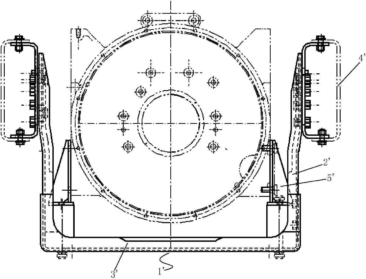
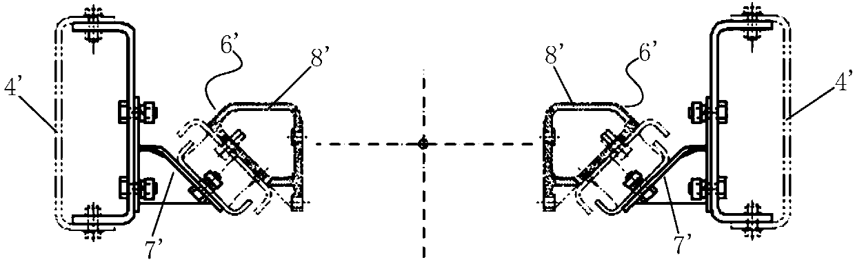
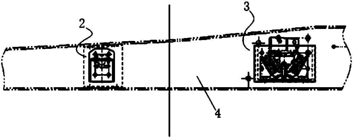
[0055] Figure 4 A schematic diagram of a powertrain mount structure proposed for a specific embodiment of the present invention; Figure 5 It is a schematic diagram of the installation structure of the front suspension and the rear suspension proposed in the specific embodiment of the present invention; Image 6 Schematic diagram of the structure of the front suspension proposed for the specific embodiment of the present invention; Figure 7 It is a schematic diagram of the installation structure of the front suspension proposed in the specific embodiment of the present invention; Figure 8 A cross-sectional view of the front suspension proposed for a specific embodiment of the present invention; Figure 9 It is a schematic diagram of the installation structure of the front suspension and...


PUM


Abstract

The invention discloses a power assembly suspension structure. The power assembly suspension structure comprises a front suspension for supporting an engine from the lower front side, a back suspension for supporting the engine from the lower back side, and an engine longitudinal beam for mounting the front suspension and the back suspension; the front suspension comprises a first lower support piece mounted on the engine longitudinal beam; a conical hole is formed in the first lower support piece; a first upper support piece is coaxially mounted in the conical hole; the outer periphery of thefirst upper support piece is of a conical structure; a first damping block is arranged between the first lower support piece and the first upper support piece; the first upper support piece is connected with the engine; the back suspension comprises a second lower support piece fixedly arranged on the engine longitudinal beam; a second damping block, a second upper support piece and a rubber padare mounted on the second lower support piece through first bolts; the section of the second upper support piece is of a trapezoidal structure; the first bolts penetrate through the lower end surfaceof the second upper support piece; and the rubber pad is positioned in the second upper support piece. The power assembly suspension structure can damp the engine to improve comfort.

Description

technical field [0001] The invention relates to the technical field of automobile suspension, in particular to a power assembly suspension structure. Background technique [0002] The powertrain mount is an important part of the engine and gearbox. In order to better adapt to harsh road conditions, the powertrain mount uses flexible materials to connect the engine, the link between the gearbox and the frame. Powertrain mounts include engine front mounts, engine rear mounts and gearbox mounts. [0003] In prior art, please refer to Figure 1 to Figure 3 , figure 1 It is a schematic diagram of the installation structure of the engine disclosed in the prior art; figure 2 A structural schematic diagram of the engine rear suspension disclosed in the prior art; image 3 It is a structural schematic diagram of the engine front suspension disclosed in the prior art; the rear suspension 1' includes a bracket connection plate 2' and a rear suspension lower support beam 3'; the br...

Claims


Application Information

Patent Timeline
IPC IPC(8): B60K5/12
CPCB60K5/1266
Inventor 张翔于建蕾王俊伟陈光明
Owner ANHUI JIANGHUAI AUTOMOBILE GRP CORP LTD
Why Eureka
Try Eureka