
Washing machine impeller and washing machine with the same

A washing machine and pulsator technology, which is applied to washing machines with containers, washing devices, textiles and papermaking, etc., can solve the problems of frequent friction between the surface of the center runner and the pulsator, low washing performance, and easy-to-stuck clothes fluff, etc. To achieve the effect of improving washing and/or drying effect, enhancing washing effect, simple and regular water flow

Active Publication Date: 2018-02-02
QINGDAO HAIER WASHING MASCH CO LTD +1
View PDF9 Cites 2 Cited by
  • Summary
  • Abstract
  • Description
  • Claims
  • Application Information

AI Technical Summary

Problems solved by technology

The pulsator of the existing pulsator washing machine generally has 3-6 stirring blade structures, and the area of ​​each stirring blade is relatively small, and the general shape is relatively flat, the washing performance is not high, and it is not conducive to the turning of the clothes. For all-in-one washing and drying machines, the drying time is poor and uneven, and a large number of wrinkles are produced
[0003] In addition, the pulsator washing machine mainly relies on the agitation of the pulsator to drive the clothes to be washed. In order to prevent entanglement, a freely rotating runner is generally installed in the middle of the pulsator. At present, most of the runners rotate along the central axis set on the pulsator, or along the The central shaft connected to the impeller rotates, and when the bottom rotates, it contacts the surface of the impeller under the action of gravity, and is subject to friction when rotating. The friction coefficient between plastics is relatively large, and there is a risk of damage after a long time; in addition, the center There is a gap between the bottom of the runner and the surface of the pulsator. When the center runner rotates, it is easy to deviate, resulting in frequent local friction between the center runner and the surface of the pulsator, resulting in abrasion or a larger gap in other directions, which is easy to get stuck on clothes or lint. , making the center wheel more frictional and more susceptible to damage

Method used


Image

  • Washing machine impeller and washing machine with the same
  • Washing machine impeller and washing machine with the same
  • Washing machine impeller and washing machine with the same

Examples


Embodiment 1

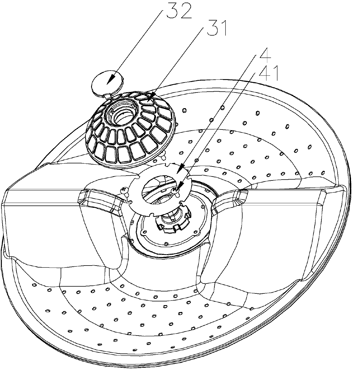
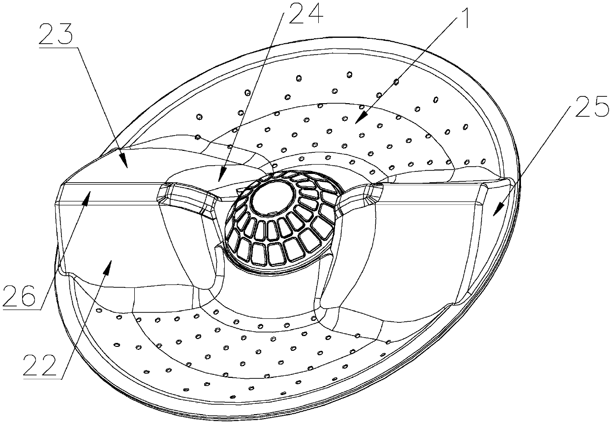
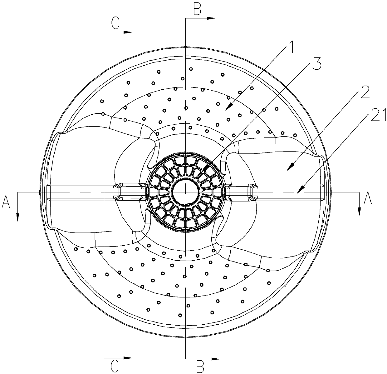
[0061] Such as Figure 1 to Figure 6 As shown, the present invention provides a pulsator for a washing machine, which includes a pulsator body 1 , a freely rotatable center wheel 3 and a smooth support structure arranged under the center wheel 3 are arranged in the center of the pulsator body 1 .

[0062] The smooth supporting structure is a metal washer 4, which is clamped on the pulsator body 1, and the center runner 3 is rotatably arranged above the metal washer 4. The diameter of the outer edge of the metal gasket 4 is greater than or equal to the outer diameter of the bottom of the center runner 3 .

[0063]The central runner 3 has a hemispherical structure, and several bumps 31 are arranged on the surface of the central runner 3 , preferably, the bumps 31 are uniformly and circumferentially arranged on the surface of the central runner 3 . Described projection 31 extends uniformly circumferentially along the center runner 3 surface, and this projection 31 is distributed...

Embodiment 2

[0065] In this embodiment, a washing machine pulsator includes a pulsator body 1, a freely rotatable center runner 3 and a smooth support structure arranged under the center runner 3 are arranged in the center of the pulsator body 1.

[0066] Compared with Embodiment 1, the difference is that the smooth support structure is a metal gasket 4, which is threaded or detachably connected to the pulsator body 1 through screws 41, and the center runner 3 is rotatably set on the metal gasket 4. Spacer 4 above. The outer edge diameter of described metal spacer 4 is greater than or equal to central runner 3 bottom outer diameters.

Embodiment 3

[0068] Such as Figure 1-6 As shown, this embodiment is a further limitation of Embodiment 1 and Embodiment 2, including a pulsator body 1 on which two raised agitators extending from the center along the radial direction of the pulsator body 1 are arranged. blade 2, the two stirring blades 2 radially extend on the same diameter.

[0069] The stirring blade 2 is wide at the bottom and gradually narrows toward the top. The stirring blade 2 includes a first side 22 and a second side 23 extending from the top 21 to the impeller chassis 11. The first side 22 and the second side are The side surfaces 23 are located on both radial sides of the stirring blade 2 , and the curves where the first side 22 and the second side 23 intersect with the impeller body 1 are substantially parallel to the radial direction of the stirring blade 2 .

[0070] The deviation angle between the curve of the first side 22 and the second side 23 intersecting the impeller body 1 and the radial direction of...


PUM


Abstract

The invention discloses a washing machine impeller and a washing machine with the same. The washing machine impeller comprises an impeller body; a center rotating wheel capable of rotating freely anda smooth supporting structure are arranged in the center of the impeller body, wherein the smooth supporting structure is arranged under the center rotating wheel so as to reduce the friction betweenthe center rotating wheel and the impeller body. As the impeller is provided with the smooth supporting structure, wear between the center rotating wheel and the impeller body is prevented; as the center rotating wheel is arranged, clothes can be easily scattered and prevented from twining, and accordingly the washing effect is improved; stirring blades have a large area and a steep appearance, space is provided for clothes to move in the upper part, the lower part and the middle part, twining is prevented, the washing and drying effects are good, and the clothes are fluffier after being dried.

Description

technical field [0001] The invention belongs to the field of washing machine devices, and in particular relates to a washing machine pulsator and the washing machine. Background technique [0002] In the current society, washing machines for household appliances have become an indispensable part of people's lives, and there are more and more types of washing machines, including pulsator washing machines, drum washing machines, washing and drying machines and so on. Among them, the pulsator washing machine is still used by a large number of customers, and a pulsator washing machine integrating washing and drying has also been developed. At the same time, customers have higher and higher requirements for the use of pulsator washing machines. The pulsator of the existing pulsator washing machine generally has 3-6 stirring blade structures, and the area of ​​each stirring blade is relatively small, and the general shape is relatively flat, the washing performance is not high, an...

Claims


Application Information

Patent Timeline
Patent Type & Authority Applications(China)
IPC IPC(8): D06F17/10D06F17/06
CPCD06F17/06D06F17/10
Inventor 程宝珍王玲臣孙广彬田云龙公涛庄仲凯
Owner QINGDAO HAIER WASHING MASCH CO LTD
Learn More