Full-automatic cement concrete pavement calender for municipal construction

A fully automatic, concrete pavement technology, applied in the direction of roads, roads, road repairs, etc., can solve the problems of easy splashing everywhere, difficult cleaning, inconvenient cleaning, etc., and achieve the effects of reasonable structure setting, improved efficiency, and convenient use

Inactive Publication Date: 2018-02-02
连应鸿
View PDF0 Cites 2 Cited by
  • Summary
  • Abstract
  • Description
  • Claims
  • Application Information

AI Technical Summary

Problems solved by technology

[0003] 1. In the existing road surface troweling machine, the troweling blade and the rotating shaft are connected by a connecting rod, and the connecting rod is connected to the troweling blade by welding or screw connection, and cement easily enters the space between the troweling blade and the connecting rod. It is inconvenient to clean the gap, and the trowel blade is not easy to disassemble after the cement solidifies;
[0004] 2. There is a protective cover around the troweling blade in the road surface troweling machine, but the protective cover is mostly a grid-shaped protective cover. When the troweling blade is troweling the road surface, it is easy to throw cement and dust through the gap on the protective cover. It is easy to splash everywhere, resulting in the need to repeatedly plaster the road surface, and it is not easy to clean when cement and dust fall on human clothes;
[0005] 3. Because the troweling blade and the rotating shaft of the road surface troweling machine are connected by a connecting rod, there is a gap at the end of the multiple troweling blades, and the cement is easy to enter the top of the troweling blade and the rotating shaft from the gap, which is not easy to clean. Inconvenience caused by polishing the road surface

Method used


Image

  • Full-automatic cement concrete pavement calender for municipal construction
  • Full-automatic cement concrete pavement calender for municipal construction
  • Full-automatic cement concrete pavement calender for municipal construction

Examples


Embodiment Construction

[0023] The following will clearly and completely describe the technical solutions in the embodiments of the present invention with reference to the accompanying drawings in the embodiments of the present invention. Obviously, the described embodiments are only some, not all, embodiments of the present invention. Based on the embodiments of the present invention, all other embodiments obtained by persons of ordinary skill in the art without making creative efforts belong to the protection scope of the present invention.

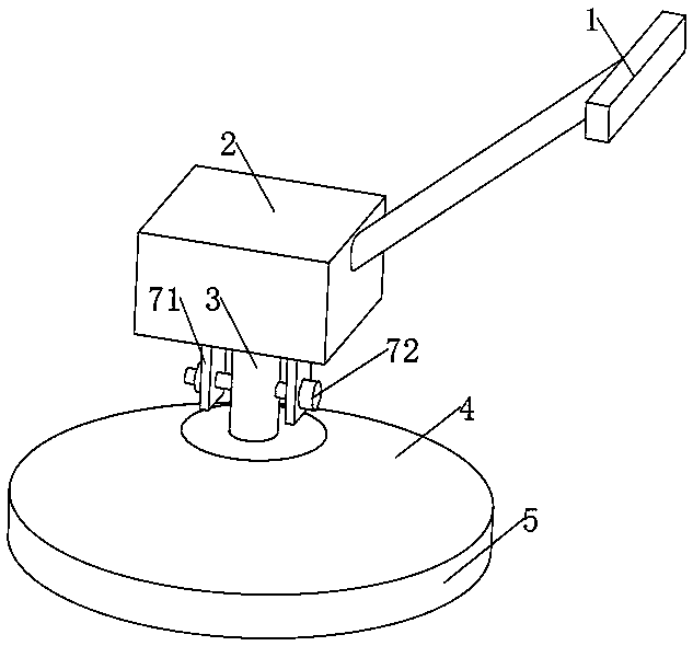
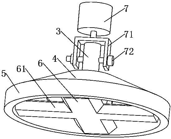
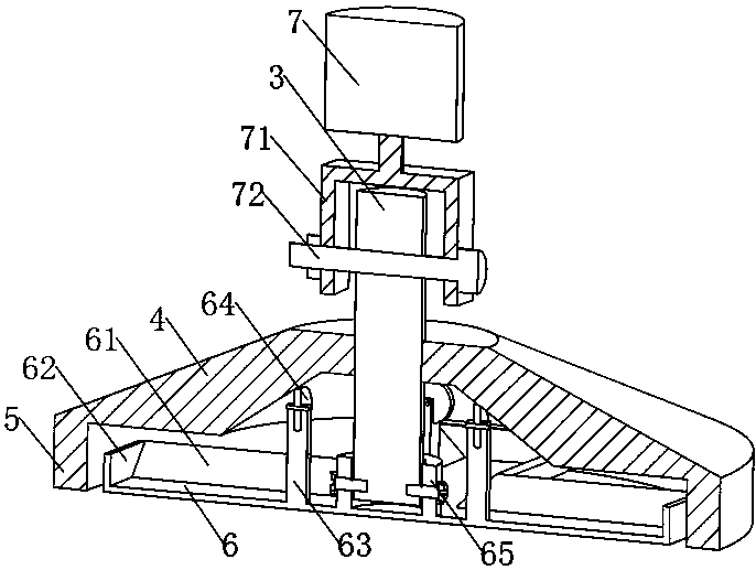
[0024] see Figure 1-4 , the present invention provides a technical solution: a fully automatic cement concrete pavement troweling machine for municipal construction, including a handle 1, a control box 2, a rotating shaft 3, a protective cover 4 and a troweling blade 6, and the handle 1 is fixed on the control box 2 On the upper right side, the control box 2 is provided with a reduction motor 7, and the transmission shaft at the lower end of the reduction mot...


PUM


Abstract

The invention discloses a fully automatic cement concrete road surface troweling machine for municipal construction, which comprises a handle, a control box, a rotating shaft, a protective cover and a trowel blade. Motor, the transmission shaft at the lower end of the deceleration motor is fixedly connected to the upper surface of the connection frame. In this device, the polishing blade and the rotating shaft are connected by connecting grooves and screws. The connecting groove is arranged in the middle of the upper surface of the polishing blade, and the connecting groove The regular groove structure replaces the connection between the trowel blade and the rotating shaft through a connecting rod. There is no gap. When the cement enters the surface of the connection groove, it is easier to clean and easy to use. The upper surface of the trowel blade is provided with a slope The vertical baffle and the vertical baffle avoid the phenomenon that most of the cement enters the upper surface of the troweling blade and falls again, which affects the smoothness of the road surface troweling. The effect of road surface troweling is better and is suitable for promotion.

Description

technical field [0001] The invention relates to the technical field of road surface troweling machines, in particular to a fully automatic cement concrete road surface troweling machine for municipal construction. Background technique [0002] The road surface troweling machine is also called the cement finishing machine. Its main structure is a trowel rotor driven by a motor or a gasoline engine. There are 2 to 4 trowels on the bottom of the cross in the middle of the rotor, which can trowel the cement concrete road surface. , but it still has the following disadvantages in actual use: [0003] 1. In the existing road surface troweling machine, the troweling blade and the rotating shaft are connected by a connecting rod, and the connecting rod is connected to the troweling blade by welding or screw connection, and cement easily enters the space between the troweling blade and the connecting rod. It is inconvenient to clean the gap, and the trowel blade is not easy to disas...

Claims


Application Information

Patent Timeline
Patent Type & Authority Applications(China)
IPC IPC(8): E01C19/42
CPCE01C19/42
Inventor 连应鸿阙智坚
Owner 连应鸿
Why Eureka
Try Eureka