
Permanent magnet transmission torque converter double-input-shaft drive device

A permanent magnet transmission, dual input shaft technology, applied in transmission, gear transmission, transmission parts, etc., can solve the problems of friction plate temperature rise, body vibration, teeth rattle and other problems, to achieve torque adjustment can be achieved. Guaranteed controllability, avoiding slippage and damage, and long service life

Pending Publication Date: 2018-02-02
宝鸡泰华磁机电技术研究所有限公司
View PDF12 Cites 2 Cited by
  • Summary
  • Abstract
  • Description
  • Claims
  • Application Information

AI Technical Summary

Problems solved by technology

But existing double clutch also has the following disadvantages simultaneously: 1, existing clutch is easy to damage, abnormal noise when shifting gears, clutch slips, friction disc temperature rises easily; 3. When the vehicle starts, the clutch combination is not smooth, causing the body to shake; 4. The output torque of the engine using the dual clutch is not easy to control and adjust, and the output power cannot be cut off as needed

Method used


Image

  • Permanent magnet transmission torque converter double-input-shaft drive device
  • Permanent magnet transmission torque converter double-input-shaft drive device

Examples


Embodiment Construction

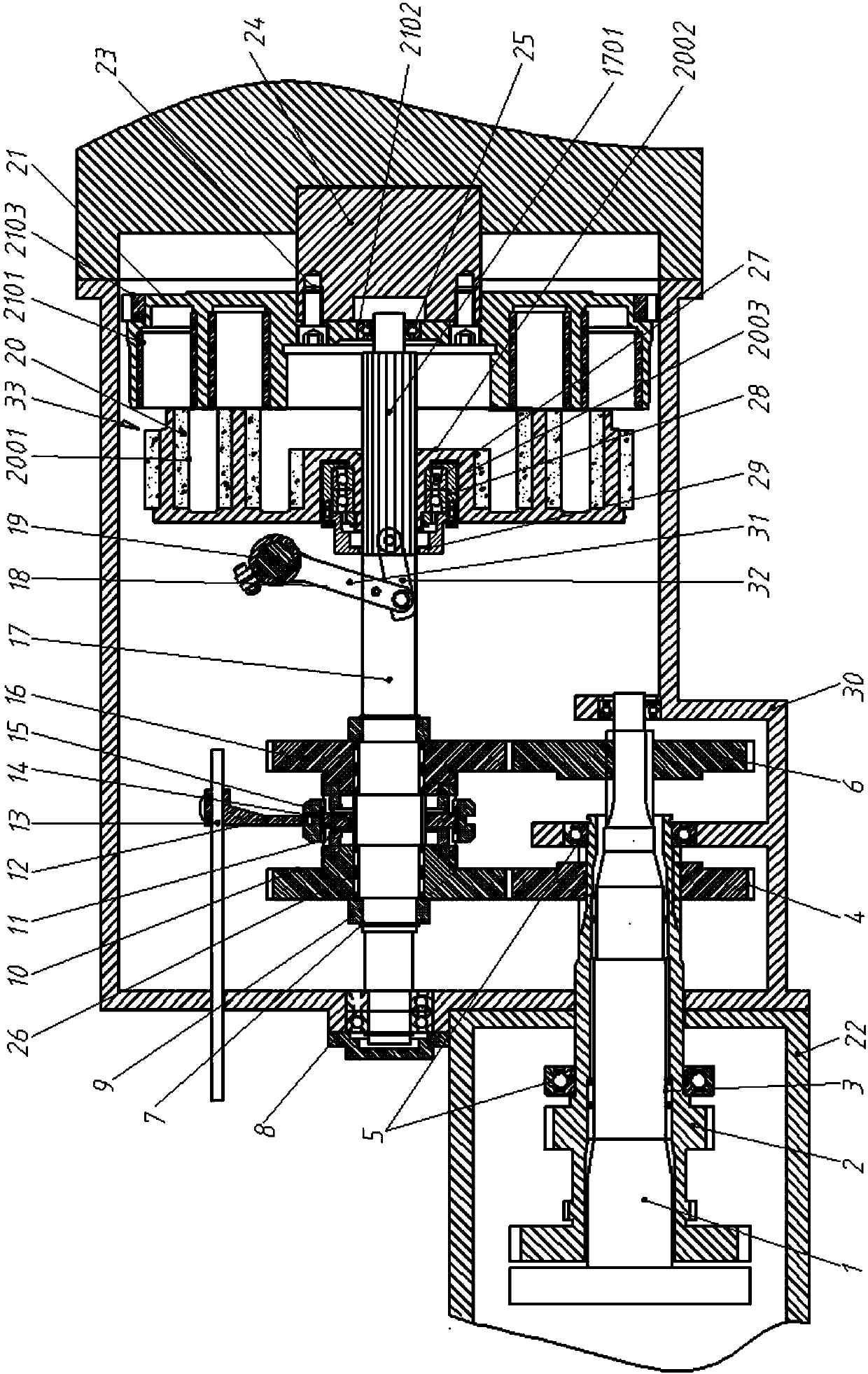
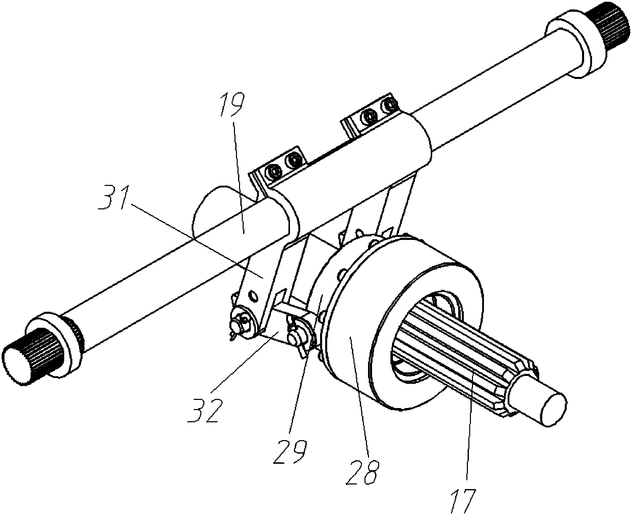
[0017] Attached below Figure 1-2 Embodiments of the present invention are described.

[0018] Permanent magnet transmission torque converter dual input shaft drives such as figure 1 As shown, it includes a housing 30 and an input shaft I1 and an input shaft II2 connected to the input end of the gearbox. The input shaft II2 is a hollow structure, and one side of the housing 30 is connected to a connecting housing 22. The input shaft II2 is supported in the casing 30 and the connection casing 22 through the bearing VI5, the input shaft I1 is rotatably supported in the inner cavity of the input shaft II2 through the bearing V3 and one end extends out of the input shaft II2, and is also rotatably supported in the casing 30 and the transmission shaft 17 between the crankshaft 24 of the engine.

[0019] One end of the transmission shaft 17 close to the engine crankshaft 24 is provided with a permanent magnet transmission torque conversion device 33, specifically, the permanent ma...


PUM


Abstract

The invention provides a permanent magnet transmission torque converter double-input-shaft drive device. The permanent magnet transmission torque converter double-input-shaft drive device comprises aninput shaft I, an input shaft II and a transmission shaft rotationally supported between a shell and a bent axle. The input shaft I is rotationally supported in an inner cavity of the input shaft II.The end, close to the bent axle, of the transmission shaft is provided with a permanent magnet transmission torque converting device. A connecting rod mechanism driving the permanent magnet transmission device for torque converting is arranged at the middle portion of the transmission shaft. A synchronous gear II and a synchronous gear I are rotationally arranged at the other end of the transmission shaft. A gear II engaged with the synchronous gear II is arranged at one end of the input shaft II, the end, stretching out of the input shaft II, of the input shaft I is provided with a gear I engaged with the synchronous gear I, and the part, between the synchronous gear II and the synchronous gear I, of the transmission shaft is provided with a synchronizer. According to the permanent magnet transmission torque converter double-input-shaft transmission device, conversion of engine power between the input shaft I and the input shaft II can be controlled, meanwhile, the engine torque canbe transmitted, control and adjustment can be conducted on the torque, and the problems that in a double clutch, skidding is likely to happen, the temperature rise of friction plates is high, separation is not thorough, gear shifting is difficult, power is interrupted, the transmission efficiency is low, and friction plates are frequently replaced are solved.

Description

technical field [0001] The invention belongs to the technical field of mechanical transmission, and in particular relates to a dual-input shaft driving device for a permanent magnet transmission torque converter. Background technique [0002] The concept of dual clutch transmission (DCT) has a history of sixty or seventy years. As early as 1939, Germany's Kegresse.A was the first to apply for a patent for a dual-clutch transmission, and proposed the design concept of dividing the manual transmission into two parts. One part transmits odd-numbered gears, and the other part transmits even-numbered gears. A clutch connects two input shafts, and the driven gears of adjacent gears are staggered to mesh with the two input shaft gears. Cooperating with the control of the two clutches, the transmission ratio can be converted without cutting off the power (there will be a short pause when the power is interrupted). Thereby shortening the shifting time and effectively improving the s...

Claims


Application Information

Patent Timeline
IPC IPC(8): F16H3/085F16H3/12F16H35/10F16H57/023H02K49/10
CPCH02K49/102H02K49/106F16H3/085F16H3/12F16H35/10F16H57/023Y02T10/62
Inventor 赵克中张琳汪洋张新龙孙婷
Owner 宝鸡泰华磁机电技术研究所有限公司
Learn More