Gas distributor
An air distributor and gas technology, which is applied to burners, gas fuel burners, combustion methods, etc., can solve the problems of insufficient combustion stability and many leakage points.
Pending Publication Date: 2018-02-02
YANTAI LONGYUAN POWER TECH
0 Cites 0 Cited by
AI-Extracted Technical Summary
Problems solved by technology
[0002] At present, the gas distribution device often adopts a multi-nozzle DC structure. When using multi-nozzle, a gas header needs to be installed to distribute the gas to each nozzle. The leakage ...
Method used
Air gun 8 is in the process of blowing gas, a part of gas is ejected to the inboard of stabilizing disk 4 by the 3rd gas spout 803, in the cavity that air gun 8 and gas distribution cylinder 1 surround, passes through stabilizing combustion after preliminary mixing with air The disc 4 is discharged into the pre-combustion chamber 3, and the swirl vane 42 is arranged in the circumferential direction of the installation disc, and the swirl vane 42 is opposed to the inner wall of the air distribution cylinder 1, and the installation disc is erected in the middle of the air distribution cylinder 1. At the same time, The mixed gas of gas and air blown in the air distribution cylinder 1 is led out by the swirl blades 42 , so that the mixed gas is led out along the direction of the swirl blades 42 . An air through hole 41 is set on the mounting plate, and the mixed gas is exported along the axial direction of the air distribution cylinder through the air through hole 41, and the mixed gas of gas and air is blown obliquely by the swirl blade 42 at a predetermined swirl angle, and passes through two Blowing at an angle makes it easy to further mix the mixed gas with the gas ejected from the second gas nozzle 802 to ensure mixing uniformity.
In a specific embodiment of the present case, the end of the air gun 8 is also set up with a disc-shaped gas ring 82 between the nozzle 81 and the inner cavity of the air gun 8, and the gas ring 82 is provided with a plurality of holes that run through its thickness direction. Gas through hole 83. After the gas is transported through the inner cavity of the air gun 8, it is sprayed by the nozzle 81. Due to the structure of the multi-stage gas nozzle of the nozzle 81, in order to avoid the gas blowing process, the first gas nozzle 801, the second gas nozzle 802 and the third gas nozzle Gas blown by the nozzle 803 causes the air pressure of the nozzle to be unstable in the direction of blowing, and a disk-shaped gas ring 82 is arranged between the nozzle 81 and the inner chamber of the air gun 8, and the gas is blown to the gas ring 82 through the inner chamber of the air gun 8. The gas through-hole 83 on the 82 leads out, thus plays the effect of throttling and stabilizing the gas. At the same time, the inside of the air gun 8 is isolated into two parts of the nozzle 81 and the inner chamber of the air gun 8 by the gas ring 82, so that the head of the air gun 8, that is, the position of the nozzle 81, forms a gas header, which is beneficial to the gas pressure at the position of the nozzle 81 of the air gun. Stable, making the gas flame more stable.
In a specific embodiment of the present case, the stable combustion plate 4 includes a mounting plate and a plurality of swirl vanes 42 arranged circumferentially around the mounting plate, and the mounting plate is provided with a flame detection conduit mounting hole for installing the flame detection conduit 5 51, the ignition gun installation hole 61 for installing the ignition gun conduit 6, the fire observation conduit installation hole 71 for installing the fire observation conduit 7, and the air gun installation hole 80 for installing the air gun 8; the mounting plate is also provided with an air through hole that runs through its thickness direction 41. The stable combustion plate 4 includes two parts: the mounting plate and the swirl vane 42. The air distribution tube 1 of the air distribution device is provided with a fire detection conduit 5, an ignition gun conduit 6 and a fire observation conduit 7. The three surround the air gun 8 and are all along the distribution tube 1, the installation plate supports the fire detection conduit 5, the ignition gun conduit 6, the fire observation conduit 7, and the air gun 8, and the fire detection conduit installation hole 51, the ignition gun installation hole 61 and the fire observation conduit are installed on it. The holes 71 ensure the structural stability of each pipeline.
In a specific embodiment of this case, the second gas nozzle 802 and the third gas nozzle 803 all include a plurality of nozzles evenly distributed in the circumferential direction of the nozzle 81, and the inner diameter d2 of the second gas nozzle 802 is greater than or equal to the third gas nozzle 803 The inner diameter d3. The second gas nozzles 802 and the third gas nozzles 803 are evenly distributed in the circumferential direction of the nozzle 81 , so that the concentration of the gas in each region of the nozzle 81 in the peripheral direction of the nozzle 81 is uniform after the gas is injected. Simultaneously, the inner diameter d2 of the second gas nozzle 802 is set to be greater than or equal to the inner diameter d3 of the third gas nozzle 803, that is, the premixed gas ejected by the third gas nozzle 803 is first mixed with air, and then discharged after the stabilizing disc 4 is further Increase the gas con...
Abstract
The invention provides a gas distributor. The gas distributor comprises a distribution cylinder used for air conveying, and an air gun erected in the axial direction of the distribution cylinder; theair outlet end of the distribution cylinder is provided with a stable combustion disc erecting and supporting a spraying head of the air gun, the spraying head is provided with a first gas spraying opening formed in the axial end of the air gun and second gas spraying openings arranged around the circumferential side wall of the spraying head, the first gas spraying opening is formed in the spraying head of the air gun and located at the shaft end of the spraying head, sprayed-out gas is directly blown to a pre-combustion chamber at the end of the distribution cylinder, the second gas sprayingopenings are formed in the circumferential direction of the spraying head, and penetrate the circumferential side wall of the spraying head, when the air gun blows the gas, gas is sprayed out in theaxial direction of the spraying head and the radial direction of the spraying had, gas sprayed out of the second gas spraying openings is mixed with air conveyed in the air distribution cylinder in advance, the ignition success rate and the combustion stability are improved, and the structural performance of the gas distributor is optimized.
Application Domain
Gaseous fuel burner
Technology Topic
Fuel gasNozzle +1
Image
Examples
- Experimental program(1)
Example Embodiment
[0025] The invention discloses a gas distributor, which optimizes the structural performance of the gas distributor.
[0026] The technical solutions in the embodiments of the present invention will be clearly and completely described below in conjunction with the accompanying drawings in the embodiments of the present invention. Obviously, the described embodiments are only a part of the embodiments of the present invention, rather than all the embodiments. Based on the embodiments of the present invention, all other embodiments obtained by those of ordinary skill in the art without creative work fall within the protection scope of the present invention.
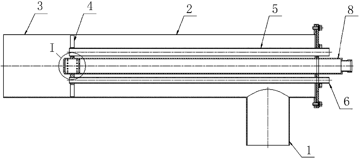
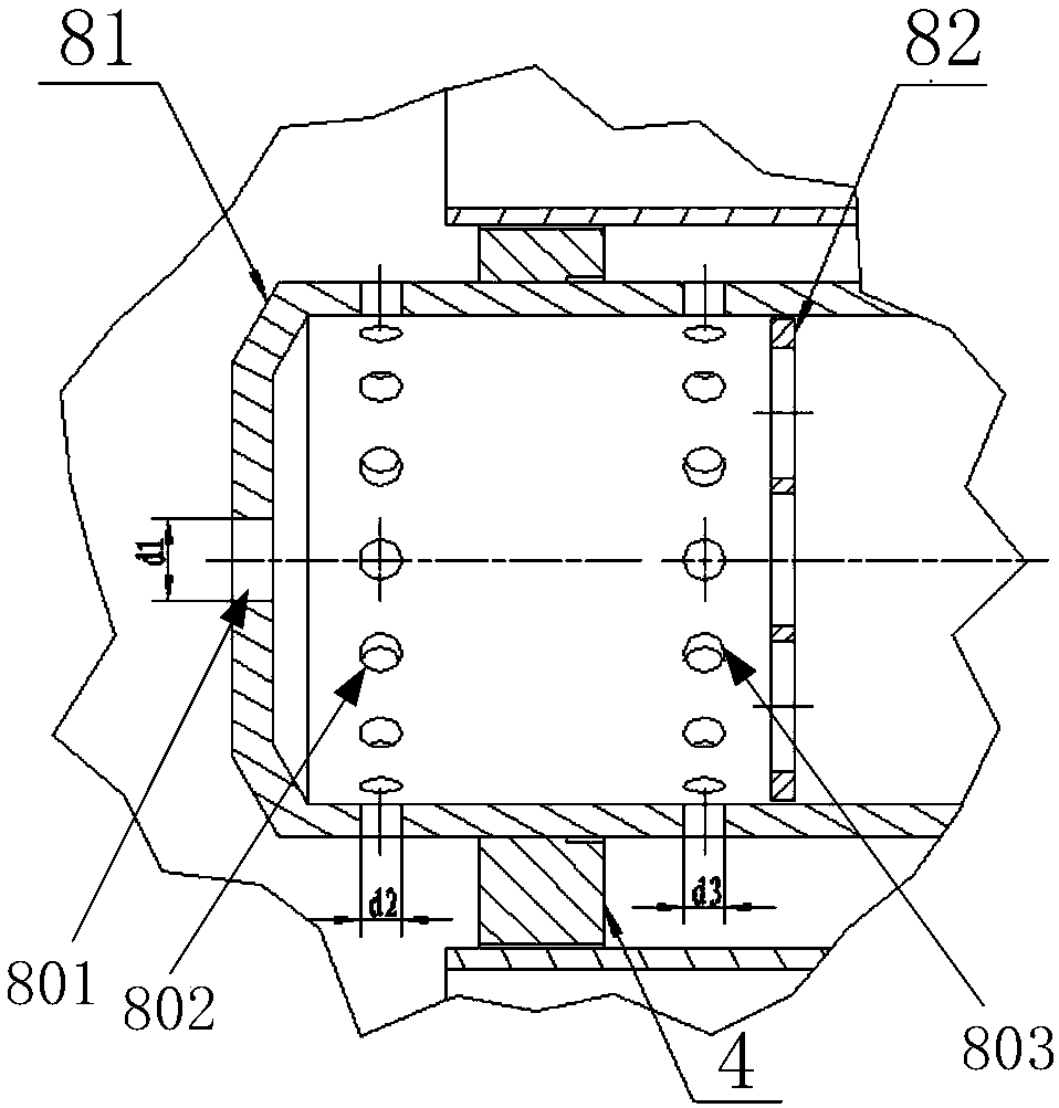
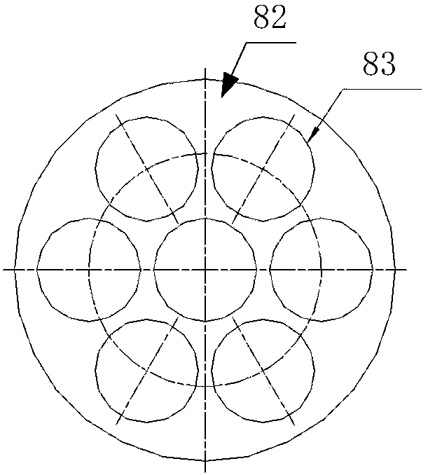
[0027] Such as Figure 1-Figure 3 As shown, figure 1 It is a schematic diagram of the structure of the gas distributor provided by the present invention; figure 2 for figure 1 A partial enlarged view of the nozzle I of the middle air gun; image 3 Yes figure 2 Schematic diagram of the gas ring structure.
[0028] The present invention provides a gas air distributor, which includes an air distribution tube 1 for air delivery, an air gun 8 erected along the axial direction of the air distribution tube 1, and a nozzle supporting the air gun 8 at the outlet end of the air distribution tube 1 In the combustion stabilizing plate 4 of 81, the nozzle 81 is provided with a first gas nozzle 801 at the axial end of the air gun 8 and a second gas nozzle 802 arranged around the circumferential side wall of the nozzle 81. The air gun 8 is erected in the air distribution tube, and the nozzle 81 of the air gun 8 is supported by the combustion stabilizing plate 4 arranged in the air distribution tube 1. The nozzle 81 is provided with a first gas nozzle 801, which is located at the shaft end of the nozzle 81 and emits The gas is blown directly into the pre-combustion chamber 3 at the end of the air distribution tube 1, a second gas nozzle 802 is opened in the circumferential direction of the nozzle 81, and the second gas nozzle 802 penetrates the circumferential side wall of the nozzle 81. When the air gun 8 blows gas , The gas is sprayed along the axial direction of the nozzle 81 and the radial direction of the nozzle 81 respectively. The gas sprayed from the second gas nozzle 802 is mixed with the air conveyed in the air distribution tube 1 in advance, which improves the ignition success rate and combustion Stability. The gas ejected from the first gas nozzle 801 improves the rigidity of the gas flame. By grading the gas nozzles of the air gun nozzle 81, the combustion stability is ensured, and only a single air gun pipe and nozzle are used to reduce The leakage point improves the safety and optimizes the structural performance of the gas distributor.
[0029] In a specific embodiment of the present case, it further includes a third gas nozzle 803 arranged around the circumferential side wall of the nozzle 81, and the second gas nozzle 802 and the third gas nozzle 803 are located on the outside and inside of the steady combustion plate 4, respectively. The second gas nozzle 802 and the third gas nozzle 803 are both arranged around the circumference of the nozzle, and are arranged at intervals along the axial direction of the nozzle 81, and are distributed on the inner and outer sides of the stabilizing plate 4, and the third gas nozzle 803 penetrates the circumference of the nozzle 81 To the side wall, when the air gun 8 blows the gas, it is first blown to the air delivery cavity between the air distribution tube 1 and the air gun 8 through the third gas nozzle 803. The air is first mixed with the gas blown from the third gas nozzle 803 to form a second The mixed gas of the first stage; the mixed gas of the first stage is blown out through the combustion stabilizing plate 4, and is further mixed with the gas ejected from the second gas nozzle 802 to increase the gas concentration to reach the ignition concentration of the gas, forming the second stage The mixed gas is conducive to successful ignition; finally the second-stage mixed gas and the gas from the first gas nozzle 801 enter the pre-combustion chamber 3 together to ensure the rigidity of the gas flame.
[0030] By arranging the gas nozzles in stages along the air conveying direction, it is conducive to the full mixing of gas and air, which greatly improves the ignition success rate and combustion stability.
[0031] In a specific embodiment of this case, both the second gas nozzle 802 and the third gas nozzle 803 include a plurality of evenly distributed in the circumferential direction of the nozzle 81, and the inner diameter d2 of the second gas nozzle 802 is greater than or equal to the inner diameter d3 of the third gas nozzle 803 . The second gas nozzle 802 and the third gas nozzle 803 are evenly distributed in the circumferential direction of the nozzle 81, so that the concentration of the gas in the circumferential direction of the nozzle 81 is the same after the gas is sprayed. At the same time, the inner diameter d2 of the second gas nozzle 802 is set to be greater than or equal to the inner diameter d3 of the third gas nozzle 803, that is, the pre-mixed gas ejected from the third gas nozzle 803 is first mixed with air, and then discharged from the stable combustion plate 4 and then further Increase the gas concentration to avoid the pre-mixed gas concentration is too low, affecting the normal ignition of the ignition gun.
[0032] The inner diameter d1 of the first gas nozzle 801, the inner diameter d2 of the second gas nozzle, and the inner diameter d3 of the third gas nozzle 803, the relationship between the inner diameters of the three is d1> d2≥d3, to ensure that the gas delivery concentration gradually increases, and the output gas ejected from the first gas nozzle 801 ensures the rigidity of the flame, which greatly improves the ignition success rate and combustion stability.
[0033] In a specific embodiment of this case, the end of the air gun 8 is also provided with a disc-shaped gas ring 82 between the nozzle 81 and the inner cavity of the air gun 8. The gas ring 82 is provided with a plurality of gas through holes penetrating the thickness direction of the gas ring 82 83. After the gas is delivered by the inner cavity of the air gun 8, the nozzle 81 is sprayed. Due to the multi-stage gas nozzle structure of the nozzle 81, in order to avoid the gas blowing process, the first gas nozzle 801, the second gas nozzle 802 and the third gas The nozzle 803 blows gas, which causes the nozzle head to be unstable in the blowing direction. A disc-shaped gas ring 82 is arranged between the nozzle 81 and the inner cavity of the air gun 8. The gas is blown to the gas ring 82 through the inner cavity of the air gun 8. The gas through hole 83 on the 82 is led out, thereby throttling and stabilizing the gas. At the same time, the gas ring 82 separates the inside of the air gun 8 into two parts, the nozzle 81 and the inner cavity of the air gun 8, so that the head of the air gun 8, that is, the position of the nozzle 81 forms a gas header, which is beneficial to the gas pressure at the position of the air gun nozzle 81 Stable, making the gas flame more stable.
[0034] Such as Figure 4-Figure 6 As shown, Figure 4 Left view of the gas distributor provided by the present invention; Figure 5 It is a schematic diagram of the stabilizing plate structure of the gas distributor of the present invention; Image 6 for Figure 5 Left view.
[0035] In a specific embodiment of this case, the combustion stabilizing disk 4 includes a mounting disk and a plurality of swirling vanes 42 arranged around the circumference of the mounting disk. The mounting disk is provided with a flame detection tube mounting hole 51 for installing the flame detection tube 5, The igniter installation hole 61 of the igniter duct 6, the fire observation duct installation hole 71 of the fire observation duct 7 and the air gun installation hole 80 of the air gun 8 are installed; the mounting plate is also provided with an air through hole 41 penetrating the thickness direction. The combustion stabilizing disc 4 includes two parts: the mounting disc and the swirling blade 42. The air distribution tube 1 of the air distributor is provided with a fire detection duct 5, a igniter duct 6 and a fire observation duct 7, and the three surround the air gun 8 along the air distribution tube The axial arrangement of 1, the mounting plate supports the fire detection tube 5, the igniter tube 6, the fire observation tube 7, and the air gun 8. The fire detection tube installation hole 51, the ignition gun installation hole 61 and the fire observation tube installation are provided on it Hole 71 ensures the structural stability of each pipeline.
[0036] When the air gun 8 blows the gas, a part of the gas is ejected through the third gas nozzle 803 to the inside of the combustion stabilization plate 4, that is, in the cavity enclosed by the air gun 8 and the gas distribution cylinder 1, and is initially mixed with air and then discharged through the stabilization plate 4 To the pre-chamber 3, by arranging the swirling vanes 42 in the circumferential direction of the installation disc, the swirling vanes 42 are against the inner wall of the air distribution tube 1, and the installation disc is erected in the middle of the air distribution tube 1. At the same time, the swirling The blades 42 lead out the mixed gas of gas and air blown in the air distribution tube 1, so that the mixed gas is guided out along the swirling blade 42. An air through hole 41 is provided on the mounting plate, and the mixed gas is led out along the axial direction of the air distribution tube through the air through hole 41, and the mixed gas of gas and air is blown out obliquely according to a predetermined swirling angle by the swirling blades 42. The angled blowing makes it easy to further mix the mixed gas with the gas ejected from the second gas nozzle 802, ensuring the uniformity of mixing.
[0037] In a specific embodiment of the present case, the guide surface of the swirl vane 42 has a guide angle α that is arranged obliquely to the axial direction of the combustion stabilizing disc. The swirling vanes 42 are evenly distributed in the circumferential direction of the mounting disc, and at the same time, the guide surface of the swirling vanes 42 and the axial direction of the combustion stabilizing disc 4 are set with a certain angle of guide inclination α, so that the airflow derived from the stabilizing disc 4 rotates The derivation structure is more conducive to achieving the mixing of the gas flow with the second gas nozzle along the radial direction of the nozzle.
[0038] Preferably, the inclination range of the diversion angle α is 30°-60°.
[0039] In a specific embodiment of this case, the swirling blades 42 include 8-56 evenly arranged in the circumferential direction of the mounting disk, and the height h between the edge of the mounting disk and the inner wall of the air distribution tube 1 is 8-56. 60mm, the width b of the swirl vane 42 is 4-16mm. The swirling blades 42 can be arranged to be welded and connected to the outer ring of the mounting disk, or a combustion stabilizing disk 4 with the same inner diameter as the air distribution tube 1 can be prefabricated, and then the swirling blade structure can be directly processed on the combustion stabilizing disk 4. The inclination direction of the swirling vanes is along the thickness direction of the combustion stabilizing disc. Specifically, the inclination angle α, number n, width b, and height h of the swirl blades are determined according to the output and combustion conditions of the air gun.
[0040] In this embodiment, the air through holes 41 include multiple groups surrounding the inner ring and the outer ring of the mounting disk. The air through holes 41 are provided with multiple circles of air through holes along the radial direction of the mounting plate to ensure structural strength and facilitate the blowing of gas.
[0041] In a specific embodiment of the present case, the second gas nozzle 802 and the third gas nozzle 803 both include multiple groups located inside and outside the steady combustion plate 4. To adapt to different combustion conditions and combustion environment needs of different air guns, the second gas nozzle 802 and the third gas nozzle 803 are set with multiple turns to control the pre-mixing amount and combustion concentration of the gas, thereby further improving the combustion of the gas distributor in the harsh environment stability.
[0042] It should be noted that the fire detection tube 5, the igniter tube 6 and the fire observation tube 7 only play a guiding role in this air distributor and are not pressure-bearing parts. A thin-walled tube can be selected; and the inside of the air gun 8 is Fuel gas needs to withstand gas pressure. As a pressure-bearing part, pipes with wall thickness that meet the pressure-bearing requirements must be selected.
[0043] The foregoing description of the disclosed embodiments enables those skilled in the art to implement or use the present invention. Various modifications to these embodiments will be obvious to those skilled in the art, and the general principles defined in this document can be implemented in other embodiments without departing from the spirit or scope of the present invention. Therefore, the present invention will not be limited to the embodiments shown in this document, but should conform to the widest scope consistent with the principles and novel features disclosed in this document.
PUM
Property | Measurement | Unit |
Width | 4.0 ~ 16.0 | mm |
Description & Claims & Application Information
We can also present the details of the Description, Claims and Application information to help users get a comprehensive understanding of the technical details of the patent, such as background art, summary of invention, brief description of drawings, description of embodiments, and other original content. On the other hand, users can also determine the specific scope of protection of the technology through the list of claims; as well as understand the changes in the life cycle of the technology with the presentation of the patent timeline. Login to view more.